
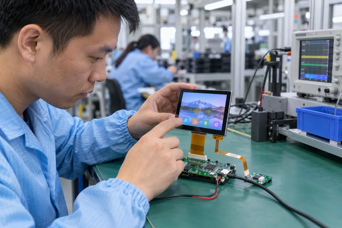
An RGB touch display module commonly uses a parallel video path that the host must drive with supported pixel timing and control signals. Touch communication remains a separately specified function. A broad ribbon connector does not prove pin compatibility, local graphics memory or complete software support. This guide checks host resources, pixel format, synchronization, power and cable routing before mounted input acceptance. It helps an OEM distinguish video-drive faults from touch mapping and avoid treating a static supplier demo as a production-ready interface.
Contents: 1 · 2 · 3 · 4 · 5 · 6 · 7 · 8 · 9 · 10
1. What does RGB describe in the quoted module?
RGB names color information in the display path, but the proposed interface needs a precise definition. A parallel streaming interface differs from a command interface that writes local graphics memory. Also, bit arrangement and control signals depend on the LCD. Confirm whether the host or module supplies display control. Keep touch and backlight functions separate. A ribbon cable photograph cannot establish the complete delivered electronic boundary.
A broad RGB label can hide different host tasks. Assuming local memory or a controller may leave a production design without necessary graphics functions.
Buyer checklist for RGB touch display module
Specify the exact RGB interface. Request the exact LCD interface definition and included-board list. Confirm display-control and memory ownership, then reconcile the quoted module with the hardware used in the demonstration.
- Interface mode
- Display-control owner
- Graphics memory
- Included boards
| Decision point | Requirement to retain | Related check |
|---|---|---|
| Failure boundary | A broad RGB label can hide different host tasks. Assuming local memory or a controller may leave a production design without necessary graphics functions. | Graphics memory |
| Approval action | Request the exact LCD interface definition and included-board list. Confirm display-control and memory ownership, then reconcile the quoted module with the hardware used in the demonstration. | Included boards |
Review the capacitive product context if glass-front or gesture operation enters the specification. capacitive touchscreen options.
2. Which host resources must be available?
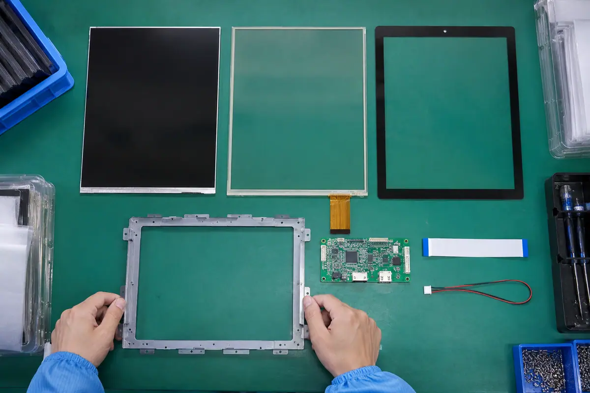
A streaming panel can require host display control, framebuffer storage and suitable transfer capacity. Meanwhile, the application updates image content on its own schedule. Static menus and animated screens create different workload conditions. Review the exact processor and memory architecture. A development board can prove feasibility only for its own resources. Keep graphics ownership explicit before selecting resolution or promising smooth application behavior.
Insufficient memory traffic can cause artifacts even with correct wiring. An evaluation board with extra resources may hide limits on the intended production host.
Which evidence should accompany the sample?
Budget the graphics resources. Review host capabilities using applicable documentation and required content. Test demanding expected screen activity, then approve resolution and resource allocation together before final module selection.
- Display peripheral
- Framebuffer storage
- Traffic capacity
- Application workload
| Decision point | Requirement to retain | Related check |
|---|---|---|
| Failure boundary | Insufficient memory traffic can cause artifacts even with correct wiring. An evaluation board with extra resources may hide limits on the intended production host. | Traffic capacity |
| Approval action | Review host capabilities using applicable documentation and required content. Test demanding expected screen activity, then approve resolution and resource allocation together before final module selection. | Application workload |
Use the pressure-input product context when a suitable blunt stylus or glove is required. resistive touchscreen options.
3. How should pixel format and color wiring match?
The source and LCD must agree on color-bit organization and supported depth. A controller may support multiple formats, but the wiring and configuration still need an exact match. Also, unused or reassigned bits require documented treatment. Solid color fields and gradients help reveal a mapping fault. Keep electrical mapping separate from application color choices. A stable image with wrong shades may reflect configuration rather than defective optics.
A bit-map mismatch can show misleading colors. Changing graphics assets to compensate can conceal the underlying interface error.
What should the test owner record?
Check the color-bit map. Compare host output and panel input maps from applicable records. Test diagnostic color fields, then correct wiring or configuration before judging LCD color quality or approving an alternate.
- Source format
- Panel format
- Bit assignment
- Diagnostic pattern
| Decision point | Requirement to retain | Related check |
|---|---|---|
| Failure boundary | A bit-map mismatch can show misleading colors. Changing graphics assets to compensate can conceal the underlying interface error. | Bit assignment |
| Approval action | Compare host output and panel input maps from applicable records. Test diagnostic color fields, then correct wiring or configuration before judging LCD color quality or approving an alternate. | Diagnostic pattern |
A bonding proposal changes the assembled optical and mechanical interface; review its construction context. fully laminated touchscreen construction.
Primary reference: ST LTDC application note. Verify its applicable scope against the proposed build.
4. What synchronization and clock parameters need review?
The LCD requires its supported pixel clock, synchronization and data-enable behavior. Active image dimensions alone do not describe the complete timing. Blanking intervals and polarity settings belong in the configuration. Meanwhile, supported modes can differ across apparently similar panels. Read host and panel documentation together. A shifting image or line artifact should trigger a timing review before replacing touch hardware or modifying the cover.
Incorrect control polarity or timing can create unstable output. Trial settings copied from another panel may work briefly without meeting the proposed LCD requirement.
Which installed detail needs approval?
Configure the full video timing. Record the applicable timing and signal-polarity configuration. Verify a stable reference pattern and repeated startup, then retain accepted parameters with the exact LCD and host references.
- Pixel clock
- Blanking intervals
- Signal polarity
- Data-enable behavior
| Decision point | Requirement to retain | Related check |
|---|---|---|
| Failure boundary | Incorrect control polarity or timing can create unstable output. Trial settings copied from another panel may work briefly without meeting the proposed LCD requirement. | Signal polarity |
| Approval action | Record the applicable timing and signal-polarity configuration. Verify a stable reference pattern and repeated startup, then retain accepted parameters with the exact LCD and host references. | Data-enable behavior |
For a machine installation, relate these checks to mounted-console and operator conditions. industrial control touchscreen context.
5. How should framebuffer size and refresh be distinguished?
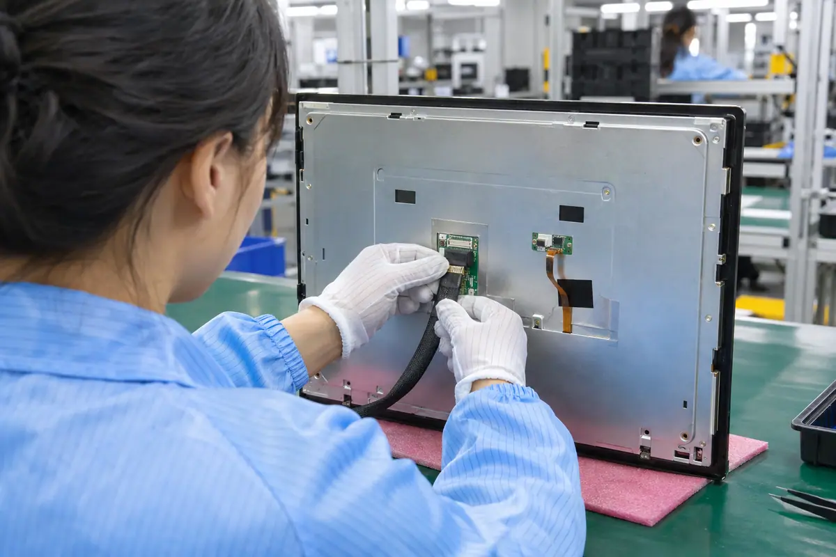
Framebuffer storage follows resolution and pixel representation, while transfer demand depends on the display mode and architecture. Also, application redraw is different from panel refresh. More buffering can support a design but creates its own memory boundary. Use host guidance rather than a universal memory claim. Test the required interface content. A touch module does not automatically include storage just because a supplier demo animates smoothly.
Confusing redraw and refresh can understate traffic or misdiagnose artifacts. Assuming included memory can leave an incomplete host design.
How can engineering close this check?
Separate storage from display transfer. Document framebuffer ownership and supported update architecture. Estimate resources using applicable host methods, then validate intended content and mode rather than extrapolating from a demonstration computer.
- Pixel representation
- Framebuffer owner
- Panel refresh
- Application redraw
| Decision point | Requirement to retain | Related check |
|---|---|---|
| Failure boundary | Confusing redraw and refresh can understate traffic or misdiagnose artifacts. Assuming included memory can leave an incomplete host design. | Panel refresh |
| Approval action | Document framebuffer ownership and supported update architecture. Estimate resources using applicable host methods, then validate intended content and mode rather than extrapolating from a demonstration computer. | Application redraw |
Healthcare equipment introduces device-specific cleaning and qualification questions; keep those outside generic component claims. medical touchscreen context.
6. What cable routing makes the parallel path reproducible?
Parallel signals need appropriate electrical design and controlled routing for the selected clock and hardware. Follow applicable guidance rather than assigning a universal safe cable length. Meanwhile, connector orientation and return paths matter. Keep production flex length and path distinct from a short bench setup. Protect bends and avoid rear-frame interference. A static continuity pass cannot establish operation under real routing and nearby switching loads.
An unapproved extension can introduce faults despite matching contacts. Tight folding or poor retention can produce intermittent video and touch cable problems.
What failure would reject this configuration?
Validate the production parallel route. Approve cable mapping, construction and routing with qualified electronics staff. Test the final length and equipment states, then retain flex and mating references for production inspection and service.
- Cable map
- Routing guidance
- Approved length
- Connector retention
| Decision point | Requirement to retain | Related check |
|---|---|---|
| Failure boundary | An unapproved extension can introduce faults despite matching contacts. Tight folding or poor retention can produce intermittent video and touch cable problems. | Approved length |
| Approval action | Approve cable mapping, construction and routing with qualified electronics staff. Test the final length and equipment states, then retain flex and mating references for production inspection and service. | Connector retention |
Compare the application boundary before assuming a single demonstration covers every installation. application solution overview.
7. Which power and backlight functions remain separate?
LCD logic, backlight drive and touch electronics can need distinct supplies or controls. Also, startup order should follow applicable component guidance. A lit backlight without a configured video path may show no useful image. Compare brightness states with touch operation because electrical conditions can change. Define who provides regulation and enable signals. A generic RGB module description cannot establish the whole power design or energy budget.
Missing a driver or control function can leave the assembly incomplete. Incorrect sequencing can look like a video-interface fault.
What should quality retain?
List every power function. Obtain power and enable requirements for each function. Test cold boot, dimming and recovery on the intended source, then retain accepted control ownership with the module interface record.
- LCD logic supply
- Backlight drive
- Touch supply
- Enable sequence
| Decision point | Requirement to retain | Related check |
|---|---|---|
| Failure boundary | Missing a driver or control function can leave the assembly incomplete. Incorrect sequencing can look like a video-interface fault. | Touch supply |
| Approval action | Obtain power and enable requirements for each function. Test cold boot, dimming and recovery on the intended source, then retain accepted control ownership with the module interface record. | Enable sequence |
Review public supplier information alongside evidence for the actual part being quoted. factory background.
8. What separate touch path must the host support?
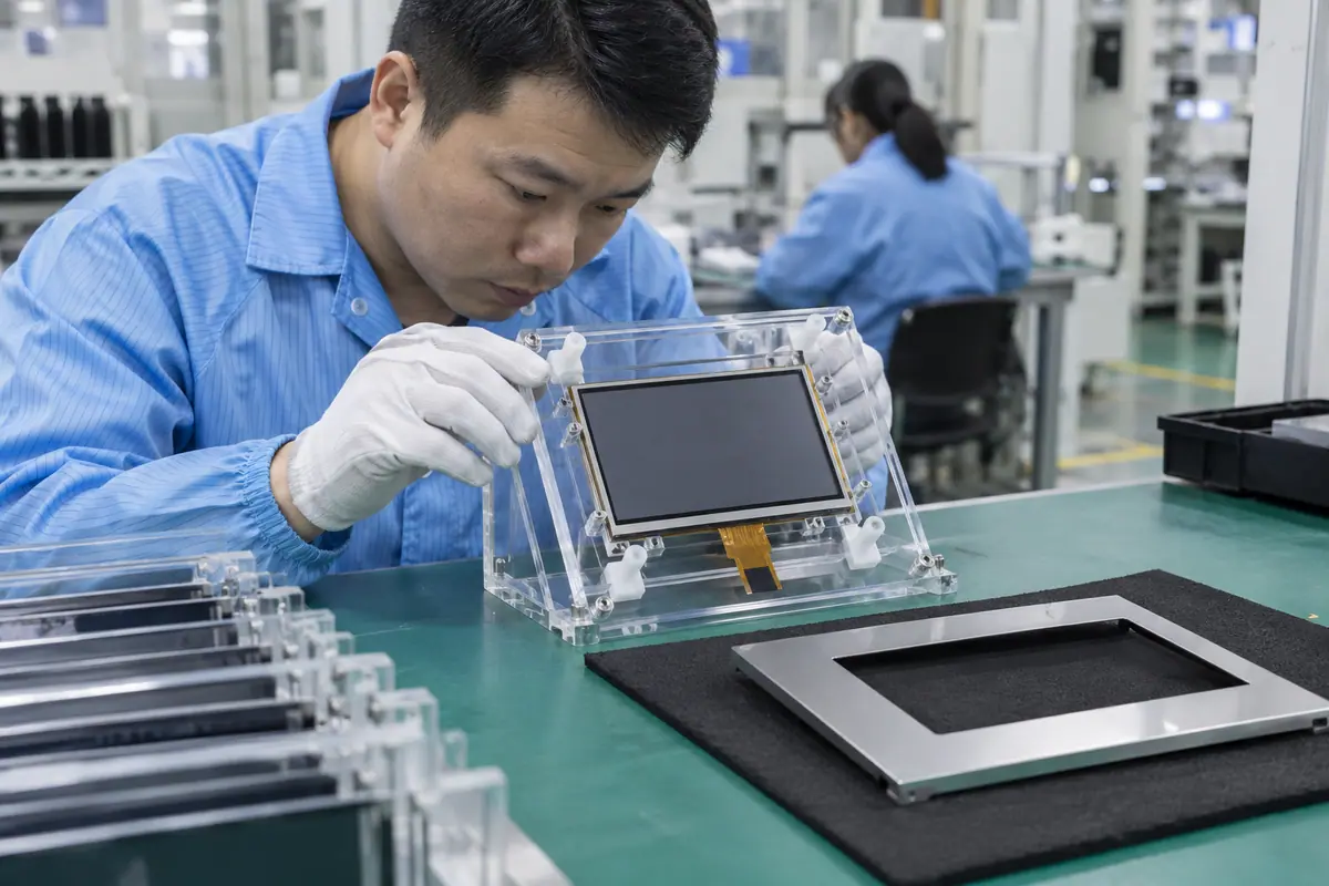
The sensor may use a suitable resistive controller or PCAP electronics with a specified host bus. RGB video does not determine either architecture. Meanwhile, coordinate transforms must follow display orientation. Check required input objects and release behavior while video operates. A display controller cannot be presumed to supply touch reports automatically. Keep firmware, driver and calibration or tuning references with the accepted sensor stack.
A correct image can coexist with absent input. Rotating video without reviewing mapping can make otherwise stable touch select the wrong target.
Which trial result changes the decision?
Validate input outside the RGB path. Identify sensor architecture, touch protocol and driver support. Test raw and application-level input on the intended host, then freeze orientation and configuration separately from video timing.
- Sensor architecture
- Touch protocol
- Host driver
- Coordinate transform
| Decision point | Requirement to retain | Related check |
|---|---|---|
| Failure boundary | A correct image can coexist with absent input. Rotating video without reviewing mapping can make otherwise stable touch select the wrong target. | Host driver |
| Approval action | Identify sensor architecture, touch protocol and driver support. Test raw and application-level input on the intended host, then freeze orientation and configuration separately from video timing. | Coordinate transform |
Send the controlled drawing and unresolved test questions with the sample configuration attached. technical inquiry route.
For example, a compact RGB module may show a stable static menu but display artifacts during heavy redraw. Review framebuffer and traffic on the intended host, then verify timing and color mapping. Keep touch event logs separate to determine whether input also changes under that workload. After correction, repeat boot and sleep recovery. This hypothetical diagnosis avoids replacing a good sensor to fix a graphics-resource problem.
9. How can display artifacts be separated from input faults?
Review power, timing, bit map and resource load for video problems. Review sensing, communication and transforms for input problems. Also, simultaneous faults can share a supply or physical cable condition. Record observations before changing parts. Use qualified staff and documented measurements for electrical checks. A moving line on the image is different from coordinate jitter. Diagnose the failed property rather than assigning every symptom to the LCD.
Random replacement can leave the actual host or mapping fault unchanged. Unrecorded fixes can make a working sample difficult to reproduce on the next unit.
How can purchasing compare the evidence?
Diagnose the property that failed. Create separate video and touch fault logs with shared hardware identity. Verify each boundary, then repeat combined operation after the documented correction rather than accepting one recovered screenshot.
- Video timing fault
- Resource fault
- Touch report fault
- Shared supply condition
| Decision point | Requirement to retain | Related check |
|---|---|---|
| Failure boundary | Random replacement can leave the actual host or mapping fault unchanged. Unrecorded fixes can make a working sample difficult to reproduce on the next unit. | Touch report fault |
| Approval action | Create separate video and touch fault logs with shared hardware identity. Verify each boundary, then repeat combined operation after the documented correction rather than accepting one recovered screenshot. | Shared supply condition |
Module quotes need a defined LCD, sensor and controller boundary. touch display module scope.
10. What should define a released RGB module?
Freeze LCD reference, video format, timing, host resources, cable and power controls. Add sensor and touch configuration as a separate linked record. By contrast, RGB touch display leaves those interfaces unresolved. Approved alternatives need difference review and relevant retests. Keep incoming and fitted tests aligned with the actual build. A later host-memory or LCD change should not silently reuse acceptance from another configuration.
A same-size LCD can need different timing or mapping. A host change can expose resource limits absent during the original trial.
What should the team release next?
Release the streaming video configuration. Send the complete video and touch release pack with the order. Require notices for relevant LCD, cable, board or software changes, then validate affected operating modes before accepting alternatives.
- LCD-format identity
- Timing and resources
- Cable-power references
- Linked touch configuration
Frequently asked questions about RGB touch display module
Q1: Does RGB mean the module includes a framebuffer? No. Confirm interface mode and graphics-memory ownership explicitly.
Q2: Is display refresh the same as application redraw? No. They describe different activities and can impose different resource demands.
Q3: What can cause stable wrong colors? A source-to-panel bit-map mismatch is one possible cause requiring documented review.
Q4: Does the RGB cable carry touch automatically? No. Identify and validate the supported touch path and its actual wiring.
Q5: What must an alternate module preserve? Supported video mode, power, physical routing and touch behavior with relevant configuration and test evidence.