
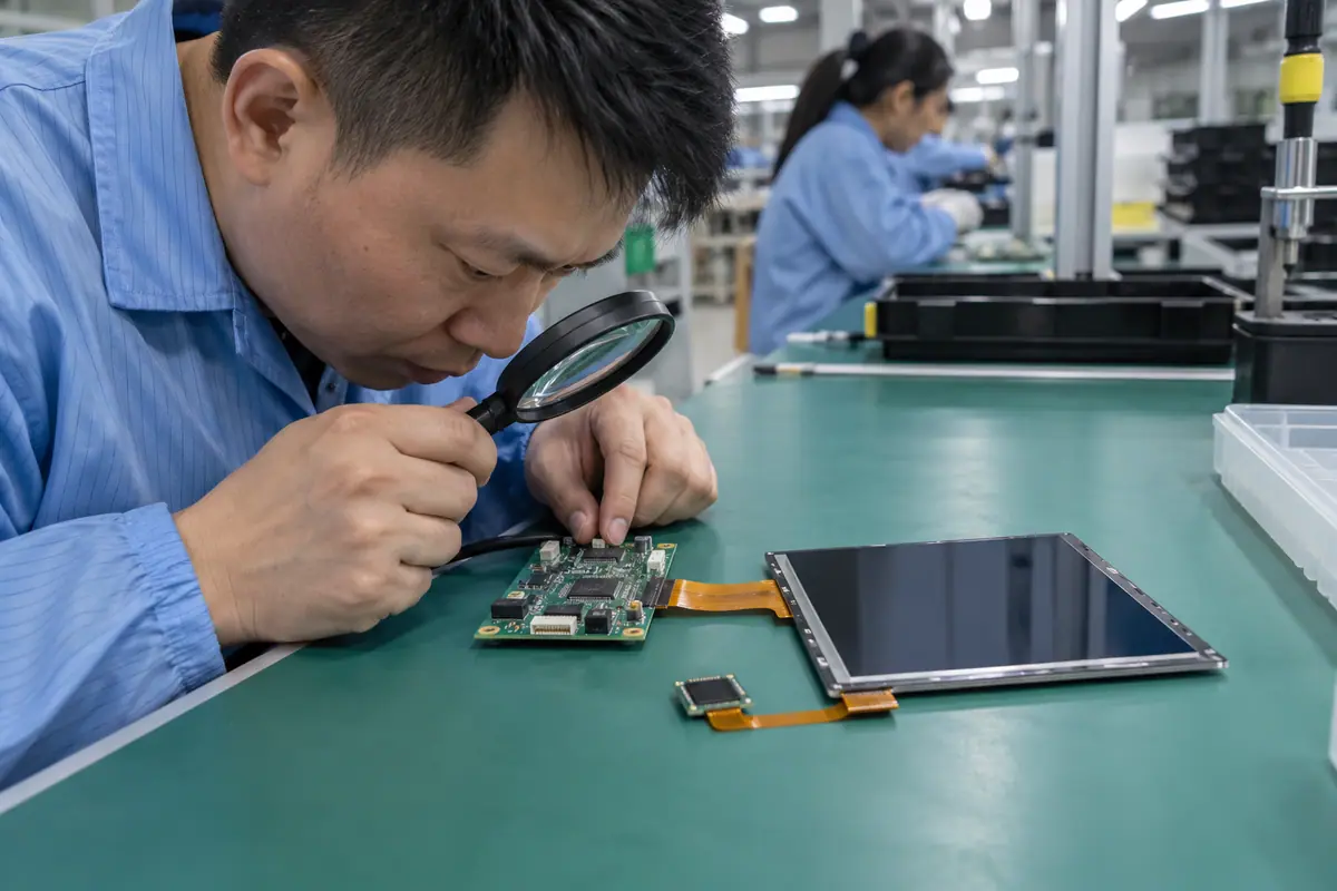
A MIPI touch display module usually needs a defined MIPI DSI video connection and a separately specified touch path. The word MIPI does not establish lane count, initialization commands or host-driver support. This guide focuses on DSI integration for an embedded OEM rather than treating every fine-pitch cable as interchangeable. It follows host capabilities, panel configuration, flex routing, power and input mapping. A working image on a supplier kit is preliminary until the production host and complete fitted stack reproduce it.
Contents: 1 · 2 · 3 · 4 · 5 · 6 · 7 · 8 · 9 · 10
1. Which MIPI interface does the module actually use?
MIPI covers multiple interfaces; a display proposal should identify its actual DSI video specification and supported physical arrangement. A camera CSI connector is not a substitute. Meanwhile, touch may use a separate controller path or an explicitly supported architecture. Request exact panel and host references. A fine-pitch flex or MIPI label cannot settle protocol compatibility, lane configuration or delivered software.
A broad interface name can conceal an unsupported host-panel pairing. Similar camera and display connectors can create dangerous assumptions about signal or power assignment.
Buyer checklist for MIPI touch display module
Identify DSI rather than a label. Require exact video and touch interface descriptions with connector maps. Review host support and panel documentation, then reject compatibility claims based only on the MIPI name or cable shape.
- Video protocol
- Physical interface
- Host support
- Separate touch path
| Decision point | Requirement to retain | Related check |
|---|---|---|
| Failure boundary | A broad interface name can conceal an unsupported host-panel pairing. Similar camera and display connectors can create dangerous assumptions about signal or power assignment. | Host support |
| Approval action | Require exact video and touch interface descriptions with connector maps. Review host support and panel documentation, then reject compatibility claims based only on the MIPI name or cable shape. | Separate touch path |
Module quotes need a defined LCD, sensor and controller boundary. touch display module scope.
2. What host and panel capabilities must agree?
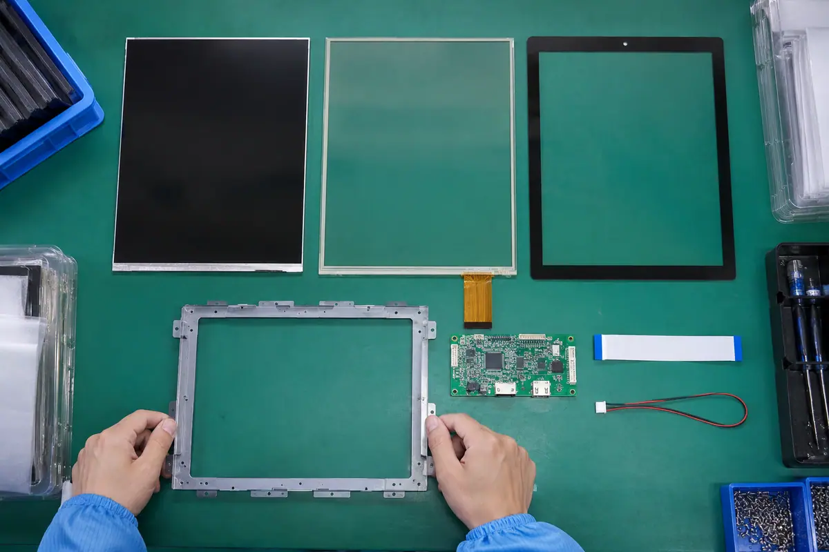
The host must support the panel operating mode, format and required link configuration. Lane arrangement and data rate need applicable documentation. Also, native resolution and refresh requirements affect the video stream. A host may support DSI yet lack a suitable driver or mode for the chosen panel. Compare exact capabilities rather than assuming every DSI display works across embedded boards. Keep production processor identity visible.
A supported connector can conceal incompatible operating mode or link requirements. An evaluation host may provide capabilities absent on the production processor.
Which evidence should accompany the sample?
Match host capability to panel mode. Compare panel requirements with the exact host documentation. Confirm operating mode, format and link configuration, then prove the intended mode on production-intent hardware before custom assembly proceeds.
- Operating mode
- Pixel format
- Lane arrangement
- Required link rate
| Decision point | Requirement to retain | Related check |
|---|---|---|
| Failure boundary | A supported connector can conceal incompatible operating mode or link requirements. An evaluation host may provide capabilities absent on the production processor. | Lane arrangement |
| Approval action | Compare panel requirements with the exact host documentation. Confirm operating mode, format and link configuration, then prove the intended mode on production-intent hardware before custom assembly proceeds. | Required link rate |
Review the capacitive product context if glass-front or gesture operation enters the specification. capacitive touchscreen options.
3. Why are initialization commands part of compatibility?
Some panels require documented command sequences, delays and configuration before normal image operation. The host driver or bridge may own those steps. Meanwhile, a vendor demonstration image can rely on unpublished setup in its firmware. Ask for the supported initialization package and reference identity. A functioning backlight does not prove that the display received correct setup. Keep startup configuration with the exact LCD revision.
A panel can remain blank despite correct physical wiring if setup is incomplete. A later LCD revision may need a different initialization sequence.
What should the test owner record?
Preserve the panel setup sequence. Obtain applicable initialization requirements and support ownership. Verify cold boot and repeated reset, then retain the accepted driver or firmware configuration with the panel part and revision.
- Command package
- Required delays
- Driver owner
- LCD revision
| Decision point | Requirement to retain | Related check |
|---|---|---|
| Failure boundary | A panel can remain blank despite correct physical wiring if setup is incomplete. A later LCD revision may need a different initialization sequence. | Driver owner |
| Approval action | Obtain applicable initialization requirements and support ownership. Verify cold boot and repeated reset, then retain the accepted driver or firmware configuration with the panel part and revision. | LCD revision |
Use the pressure-input product context when a suitable blunt stylus or glove is required. resistive touchscreen options.
Primary reference: MIPI Display Serial Interface overview. Verify its applicable scope against the proposed build.
4. How should timing and link configuration be reviewed?
Use native display requirements and supported host modes rather than guessing from active pixels alone. Video blanking and selected operating mode affect configuration. Also, bridge implementations can introduce their own limits. Review actual documentation before adjusting link parameters. A stable simple pattern provides useful starting evidence. Keep frame behavior and image alignment separate from touch coordinates. An output mode supported by one kit may not be available on another host.
Incorrect configuration can cause missing images or intermittent artifacts. Trial-and-error settings without documentation make production and later repairs difficult to reproduce.
Which installed detail needs approval?
Use a documented operating mode. Record resolution, mode and approved link parameters with the host owner. Test representative content and restart behavior, then validate any bridge limits against the accepted configuration.
- Native resolution
- Video timing
- Link parameters
- Bridge limits
| Decision point | Requirement to retain | Related check |
|---|---|---|
| Failure boundary | Incorrect configuration can cause missing images or intermittent artifacts. Trial-and-error settings without documentation make production and later repairs difficult to reproduce. | Link parameters |
| Approval action | Record resolution, mode and approved link parameters with the host owner. Test representative content and restart behavior, then validate any bridge limits against the accepted configuration. | Bridge limits |
A bonding proposal changes the assembled optical and mechanical interface; review its construction context. fully laminated touchscreen construction.
5. What flex and connector details deserve electrical review?
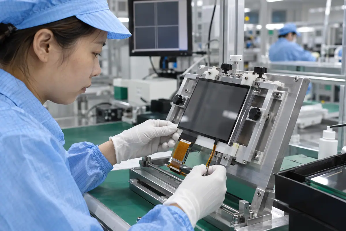
Fine-pitch flexes need exact signal assignment, contact orientation and mating references. Display signals, power and control lines can share one connector. Meanwhile, touch may exit through another tail. Follow applicable routing and bend guidance for the chosen interface. Do not infer a safe extension length from a general DSI label. Protect exits and avoid folding across sharp frame edges. Compare production routing with the short evaluation connection.
A matching flex connector can carry different supplies or signals. Unapproved extensions and sharp folds can create faults even when initial communication works.
How can engineering close this check?
Control the fine-pitch interconnect. Approve connector-face maps and cable construction with qualified electronics staff. Validate the production length and route, then retain mating and flex revisions in the release pack.
- Signal map
- Contact orientation
- Cable construction
- Approved route
| Decision point | Requirement to retain | Related check |
|---|---|---|
| Failure boundary | A matching flex connector can carry different supplies or signals. Unapproved extensions and sharp folds can create faults even when initial communication works. | Cable construction |
| Approval action | Approve connector-face maps and cable construction with qualified electronics staff. Validate the production length and route, then retain mating and flex revisions in the release pack. | Approved route |
For a machine installation, relate these checks to mounted-console and operator conditions. industrial control touchscreen context.
6. How should power, reset and sleep be coordinated?
Panel supplies, reset, initialization and backlight control may need a defined order. Touch electronics have their own startup requirements. Also, sleep recovery can differ from cold boot. Follow component and host guidance rather than copying a sequence from another display. Record whether rails remain active and who controls reset. A module that resumes only after manual power cycling may not meet intended operation.
A sequencing fault can masquerade as link incompatibility. Correct cold boot alone cannot establish repeatable wake or reconnect behavior.
What failure would reject this configuration?
Test wake separately from cold boot. Map supply and control ownership for both functions. Test cold boot, sleep and restart on the intended host, then freeze accepted sequence and configuration references before release.
- Supply owner
- Reset control
- Backlight enable
- Sleep recovery
| Decision point | Requirement to retain | Related check |
|---|---|---|
| Failure boundary | A sequencing fault can masquerade as link incompatibility. Correct cold boot alone cannot establish repeatable wake or reconnect behavior. | Backlight enable |
| Approval action | Map supply and control ownership for both functions. Test cold boot, sleep and restart on the intended host, then freeze accepted sequence and configuration references before release. | Sleep recovery |
Healthcare equipment introduces device-specific cleaning and qualification questions; keep those outside generic component claims. medical touchscreen context.
7. Which software artifacts must the OEM retain?
The integration may need a panel driver, configuration data, operating-system description and touch driver. Exact requirements depend on the host platform. Meanwhile, a supplier binary or demo image can hide those artifacts. Ask for supported versions and maintenance responsibility. A video tutorial is not a versioned release package. Keep panel-specific settings separate from application graphics while linking both to the accepted hardware configuration.
A lost configuration can prevent replacement units from starting. An operating-system update may alter behavior despite unchanged physical components.
What should quality retain?
Keep the supported software package. Agree on supported software artifacts and ownership. Retain version identities and a recovery route within approved access boundaries, then retest relevant host updates before treating them as equivalent.
- Panel driver
- Configuration data
- Touch driver
- Maintenance owner
| Decision point | Requirement to retain | Related check |
|---|---|---|
| Failure boundary | A lost configuration can prevent replacement units from starting. An operating-system update may alter behavior despite unchanged physical components. | Touch driver |
| Approval action | Agree on supported software artifacts and ownership. Retain version identities and a recovery route within approved access boundaries, then retest relevant host updates before treating them as equivalent. | Maintenance owner |
Compare the application boundary before assuming a single demonstration covers every installation. application solution overview.
8. How should touch operate alongside DSI video?
The touch controller needs its own protocol and coordinate mapping unless the supplied design explicitly combines functions through a supported architecture. DSI video alone does not prove that path. Also, rotation and multi-display use can change mapping requirements. Test raw reports, release and required gestures. Keep controller firmware with the complete stack. A working image can coexist with absent touch communication or wrong application targets.
Assuming automatic touch support leaves integration unfinished. A rotated panel can display correctly while input still follows the original orientation.
Which trial result changes the decision?
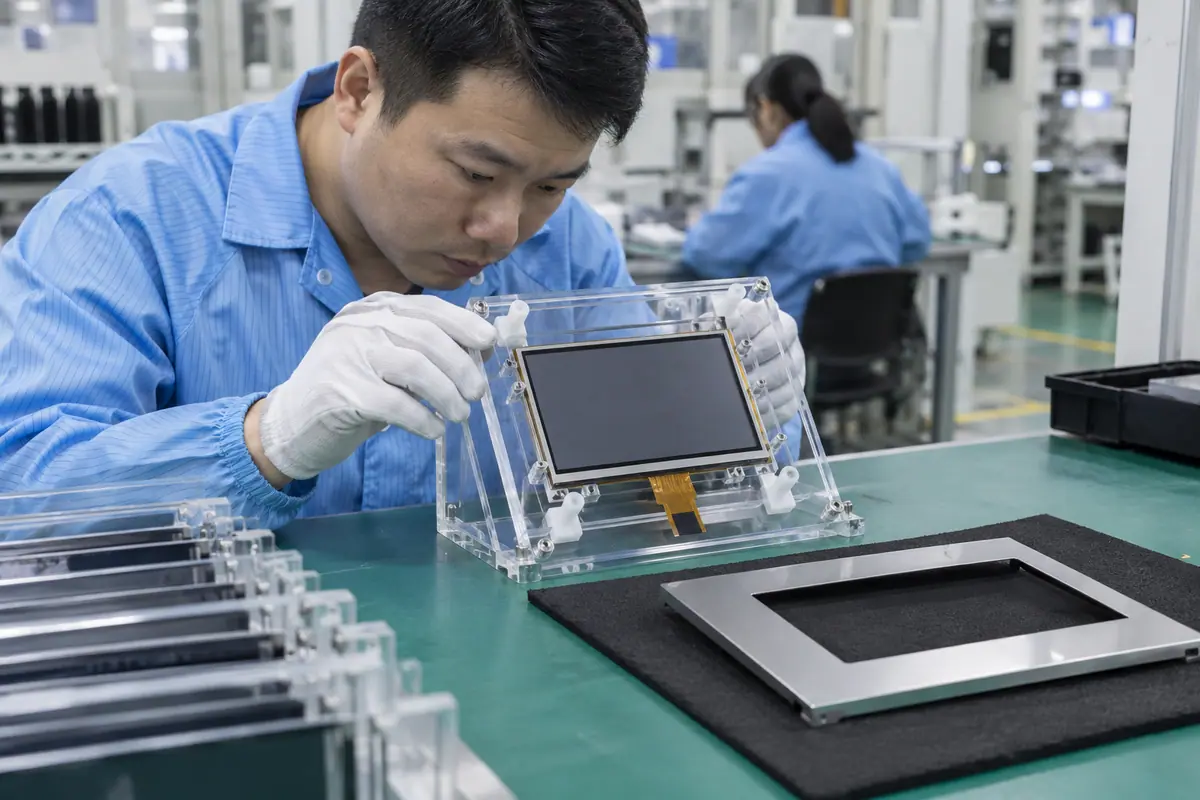
Validate the stated touch path. Identify the actual touch path and driver requirements. Verify boot, rotation and required tasks on the production host, then retain touch configuration separately from the DSI panel setup.
- Touch protocol
- Controller firmware
- Coordinate mapping
- Required gesture reports
| Decision point | Requirement to retain | Related check |
|---|---|---|
| Failure boundary | Assuming automatic touch support leaves integration unfinished. A rotated panel can display correctly while input still follows the original orientation. | Coordinate mapping |
| Approval action | Identify the actual touch path and driver requirements. Verify boot, rotation and required tasks on the production host, then retain touch configuration separately from the DSI panel setup. | Required gesture reports |
Review public supplier information alongside evidence for the actual part being quoted. factory background.
For example, a compact device may show a new DSI panel correctly on a supplier board but remain blank on its production processor. Confirm supported mode and panel initialization before changing the optical stack. Review exact flex mapping and startup controls with qualified electronics staff. After image recovery, test touch orientation and sleep wake separately. This hypothetical sequence avoids treating a supplier demonstration as universal host compatibility.
9. How can blank or unstable output be investigated?
Start with safe power and reset checks, then review initialization, operating mode and interconnect. Use qualified electronics staff for relevant measurements. Meanwhile, keep original settings and failure observations before changing parameters. A known-good compatible panel or host can help isolate a boundary. Do not improvise connector swaps based on similar shape. Record which correction closes the failure so repeat assembly has a documented configuration.
Random driver or cable changes can hide the cause. A sample made to work with unrecorded settings cannot support reproducible production approval.
How can purchasing compare the evidence?
Follow a controlled startup fault path. Create a fault log naming host, panel, cable and software versions. Verify each boundary using applicable guidance, then repeat image, wake and touch trials after the documented correction.
- Power and reset
- Initialization evidence
- Mode configuration
- Interconnect evidence
| Decision point | Requirement to retain | Related check |
|---|---|---|
| Failure boundary | Random driver or cable changes can hide the cause. A sample made to work with unrecorded settings cannot support reproducible production approval. | Mode configuration |
| Approval action | Create a fault log naming host, panel, cable and software versions. Verify each boundary using applicable guidance, then repeat image, wake and touch trials after the documented correction. | Interconnect evidence |
Send the controlled drawing and unresolved test questions with the sample configuration attached. technical inquiry route.
10. What should a MIPI module release preserve?
Freeze panel, host capability, initialization, link parameters, flex and separate touch configuration. Include power and installed acceptance results. By contrast, MIPI touch display says too little for repeat supply. Approved alternatives need explicit compatibility review. A later software or LCD change can require renewed startup and input trials. Keep ownership for those changes visible to engineering, procurement and service teams.
A same-size DSI panel may need different commands or link settings. An unreviewed host update can invalidate accepted startup and mapping.
What should the team release next?
Release the supported host-panel setup. Send the complete interface and software reference pack with the order. Require notices for relevant panel, cable, firmware or host changes, then revalidate affected modes before approving alternatives.
- Panel-host identity
- Initialization and mode
- Flex reference
- Touch and change controls
Frequently asked questions about MIPI touch display module
Q1: Does MIPI mean any fine-pitch connector works? No. Exact protocol, signal map, supplies and supported physical configuration must match.
Q2: Can a camera CSI port drive a DSI panel directly? Do not assume interchangeability. Review the distinct supported interface functions and applicable hardware design.
Q3: Why can a powered backlight accompany a blank image? The video path or panel initialization may remain incomplete despite backlight operation.
Q4: Does DSI guarantee touch communication? No. Identify and validate the actual supported touch path separately.
Q5: What makes an alternate panel acceptable? Documented host, mode, initialization, interconnect and touch compatibility with applicable fitted tests.