
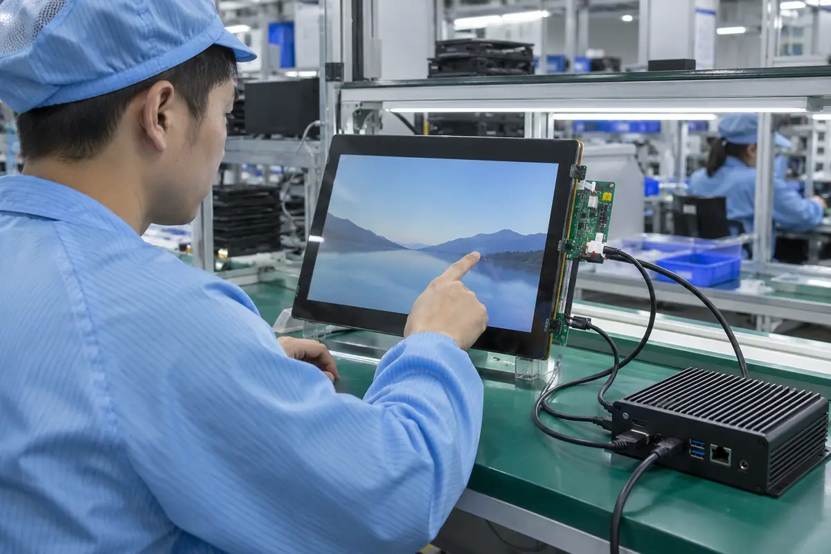
An HDMI touch display module needs a compatible video bridge or display electronics plus a separately supported touch connection. HDMI video alone does not establish USB touch, power supply or complete host-driver compatibility. This guide focuses on the delivered board and cable boundary for OEM equipment. It checks accepted video modes, startup negotiation, input mapping and installed service access. A working desktop demonstration becomes useful evidence only when the intended computer, cables, firmware and module reproduce the same behavior.
Contents: 1 · 2 · 3 · 4 · 5 · 6 · 7 · 8 · 9 · 10
1. What hardware makes the module an HDMI input assembly?
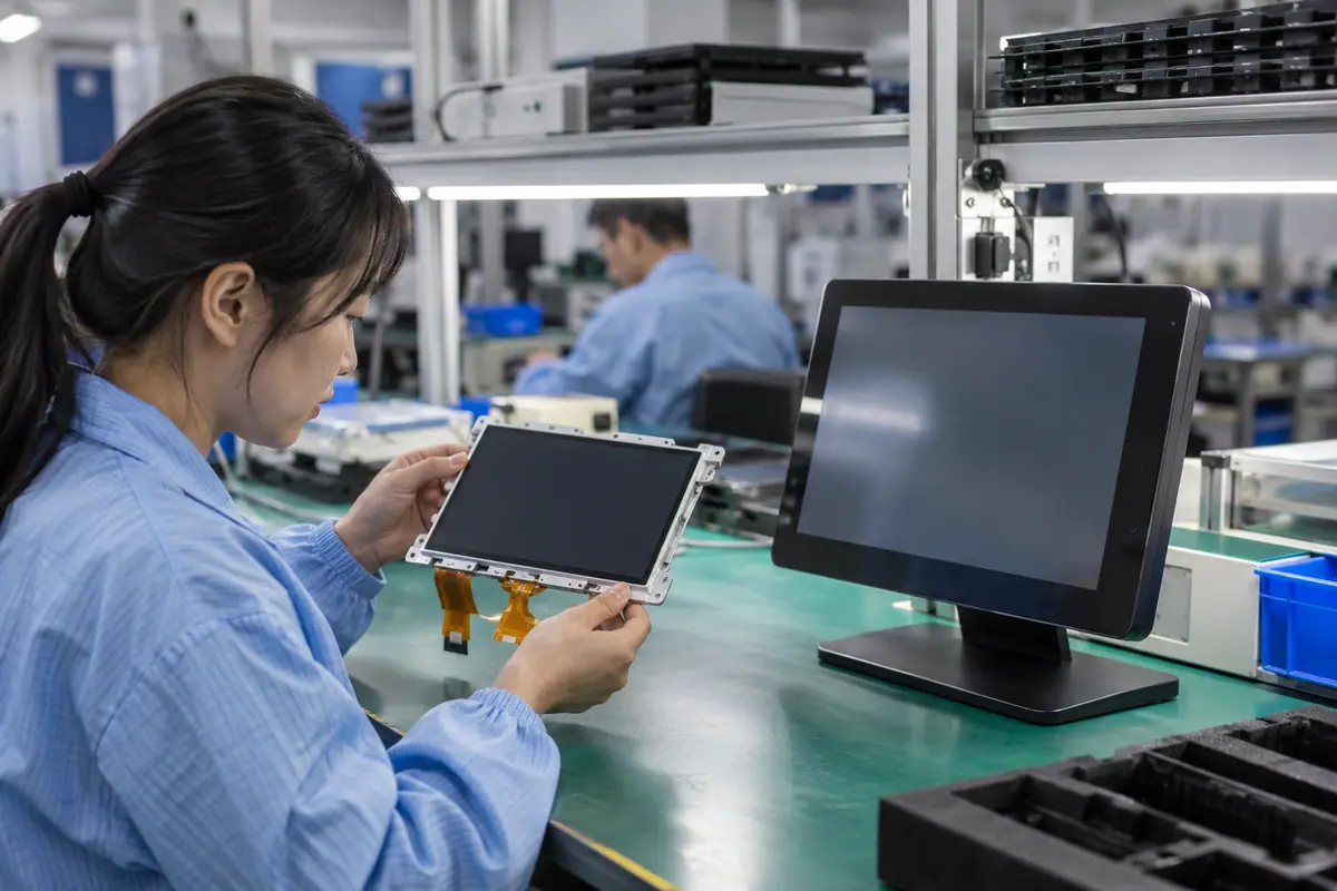
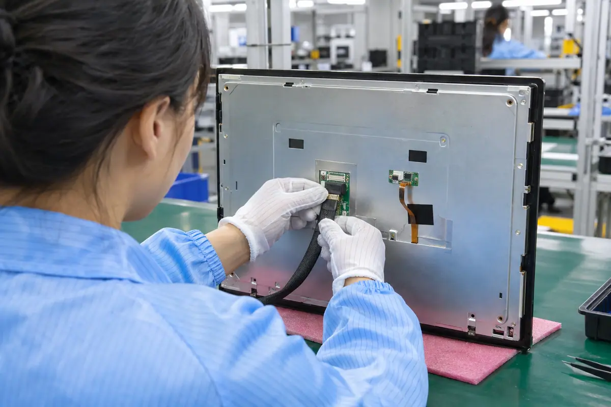
An LCD that lacks native HDMI needs suitable electronics to receive and convert the source video. The board must support the exact panel configuration. Meanwhile, touch and backlight functions may remain separate. Identify included boards, firmware and cables in the offer. A demonstration adapter should not disappear from production scope. Keep LCD and bridge part references linked because a compatible input connector does not qualify every output panel.
An HDMI module quote can omit the required conversion board or its configuration. A generic adapter may accept video while driving the wrong LCD format.
Buyer checklist for HDMI touch display module
Identify the board behind the port. Request a delivered-parts matrix and board-to-panel pairing record. Verify production electronics against the sample, then compare offers including video conversion, touch and power duties.
- HDMI receiver scope
- LCD pairing
- Bridge configuration
- Separate touch electronics
| Decision point | Requirement to retain | Related check |
|---|---|---|
| Failure boundary | An HDMI module quote can omit the required conversion board or its configuration. A generic adapter may accept video while driving the wrong LCD format. | Bridge configuration |
| Approval action | Request a delivered-parts matrix and board-to-panel pairing record. Verify production electronics against the sample, then compare offers including video conversion, touch and power duties. | Separate touch electronics |
Use the pressure-input product context when a suitable blunt stylus or glove is required. resistive touchscreen options.
2. Which video modes must source and module share?
Compare required resolution, refresh and format with the source and supplied electronics. A connector name does not establish every supported mode. Also, scaling or native-mode behavior can affect fine content. Use panel-specific and bridge-specific documentation rather than an advertised interface-version headline. Test the intended application output. A colorful demonstration at one mode cannot prove support for another production configuration.
A source may choose an unsupported or poorly scaled mode. An interface-version label can hide limits in the actual receiver, bridge or LCD.
Which evidence should accompany the sample?
Approve modes rather than version slogans. List required source modes and obtain the module support record. Verify native image geometry and content at those modes, then retain source and bridge configuration with sample acceptance.
- Source mode
- Receiver support
- Native LCD mode
- Scaling behavior
| Decision point | Requirement to retain | Related check |
|---|---|---|
| Failure boundary | A source may choose an unsupported or poorly scaled mode. An interface-version label can hide limits in the actual receiver, bridge or LCD. | Native LCD mode |
| Approval action | List required source modes and obtain the module support record. Verify native image geometry and content at those modes, then retain source and bridge configuration with sample acceptance. | Scaling behavior |
A bonding proposal changes the assembled optical and mechanical interface; review its construction context. fully laminated touchscreen construction.
3. How should EDID and startup negotiation be tested?
Display identification can influence the mode selected by a computer. The supplied electronics may provide identification data for its supported configuration. Meanwhile, startup, reconnect and sleep can trigger different behavior. Test the actual host rather than assuming every computer chooses the same mode. Keep any bridge configuration or identification revision visible. A manual display-setting adjustment during a demo should enter the acceptance record, not remain hidden.
A module can work after manual setup but fail normal startup. A changed identification package may alter host mode selection without a visible hardware change.
What should the test owner record?
Test the automatic mode path. Ask for supported identification and mode behavior. Test cold boot, reconnect and wake on the intended host, then retain accepted source settings and configuration identity in the release pack.
- Identification data
- Cold boot
- Reconnect
- Host-selected mode
| Decision point | Requirement to retain | Related check |
|---|---|---|
| Failure boundary | A module can work after manual setup but fail normal startup. A changed identification package may alter host mode selection without a visible hardware change. | Reconnect |
| Approval action | Ask for supported identification and mode behavior. Test cold boot, reconnect and wake on the intended host, then retain accepted source settings and configuration identity in the release pack. | Host-selected mode |
For a machine installation, relate these checks to mounted-console and operator conditions. industrial control touchscreen context.
Primary reference: HDMI official technology overview. Verify its applicable scope against the proposed build.
4. What power and backlight scope should the buyer confirm?
The assembly needs defined power for receiver electronics, LCD, backlight and touch. An HDMI connector does not establish a complete module supply path. Also, an adapter or host-powered touch connection may have separate limits. Confirm included regulation and connectors from applicable documentation. Check startup with the intended source and supply. A lit backlight alone cannot prove video conversion or touch communication is operating correctly.
An omitted power adapter or driver can leave the quoted assembly incomplete. A replacement supply can change noise, startup or input behavior.
Which installed detail needs approval?
List power outside the video cable. Obtain supply and control requirements for each function. Verify included power hardware, then test startup, brightness and touch on the intended supply before comparing total module consumption.
- Receiver supply
- LCD supply
- Backlight control
- Touch supply boundary
| Decision point | Requirement to retain | Related check |
|---|---|---|
| Failure boundary | An omitted power adapter or driver can leave the quoted assembly incomplete. A replacement supply can change noise, startup or input behavior. | Backlight control |
| Approval action | Obtain supply and control requirements for each function. Verify included power hardware, then test startup, brightness and touch on the intended supply before comparing total module consumption. | Touch supply boundary |
Healthcare equipment introduces device-specific cleaning and qualification questions; keep those outside generic component claims. medical touchscreen context.
5. Which touch connection belongs beside HDMI?
Many proposed assemblies use a separate USB touch link; others need their explicitly supported touch path. Confirm the actual controller protocol rather than assuming one arrangement universally. Meanwhile, USB device recognition does not prove correct mapping or gestures. Keep firmware, operating-system support and supplied cables visible. HDMI image success closes only the video check. Test raw touch reports and final application selection separately.
An HDMI cable connected alone can leave touch unavailable. A recognized touch controller may still lack required driver support on the intended operating system.
How can engineering close this check?
Connect the actual touch path. Request the touch protocol and supported host requirements. Verify input on the actual computer and cables, then reconcile driver, firmware and controller scope with the quotation.
- Touch protocol
- Supported host
- Controller firmware
- Supplied touch cable
| Decision point | Requirement to retain | Related check |
|---|---|---|
| Failure boundary | An HDMI cable connected alone can leave touch unavailable. A recognized touch controller may still lack required driver support on the intended operating system. | Controller firmware |
| Approval action | Request the touch protocol and supported host requirements. Verify input on the actual computer and cables, then reconcile driver, firmware and controller scope with the quotation. | Supplied touch cable |
Compare the application boundary before assuming a single demonstration covers every installation. application solution overview.
6. How should multiple displays and rotation be handled?
Touch mapping must identify the intended visible display and orientation. A host with several monitors may send input to another screen. Also, rotating video can require a coordinate transform. Check extended and duplicate display modes where they enter intended use. Avoid manual adjustments that are absent from the product setup procedure. A correct raw sensor report cannot decide which application window should receive its event.
A working single-monitor demo can hide wrong multi-display mapping. Unrecorded orientation settings can make serviced units behave differently from the original sample.
What failure would reject this configuration?
Map input to the intended image. Define supported display arrangements with the software owner. Test known targets after boot, rotation and reconnect, then retain mapping settings and setup procedures with the host configuration.
- Display identity
- Extended or duplicate mode
- Rotation transform
- Setup procedure
| Decision point | Requirement to retain | Related check |
|---|---|---|
| Failure boundary | A working single-monitor demo can hide wrong multi-display mapping. Unrecorded orientation settings can make serviced units behave differently from the original sample. | Rotation transform |
| Approval action | Define supported display arrangements with the software owner. Test known targets after boot, rotation and reconnect, then retain mapping settings and setup procedures with the host configuration. | Setup procedure |
Review public supplier information alongside evidence for the actual part being quoted. factory background.
7. What cable and connector conditions need validation?
Use appropriate video and touch cables for the selected modes and installation. Follow applicable supplier guidance rather than assuming every long extension will work. Meanwhile, connector retention, access and bend path matter inside equipment. Compare actual production routing with the short demo setup. Identify adapters and extension boundaries explicitly. Static continuity or a cable label alone does not establish complete operation on the chosen host and receiver.
A cable-dependent image fault can appear only after installation. Poor retention can disconnect touch while video remains normal or vice versa.
What should quality retain?
Validate the installed cable set. Approve cable references and the fitted route. Test required modes and host recovery using those cables, then retain extension approval and connector-access details for production and service.
- Video cable reference
- Touch cable reference
- Extension boundary
- Connector retention
| Decision point | Requirement to retain | Related check |
|---|---|---|
| Failure boundary | A cable-dependent image fault can appear only after installation. Poor retention can disconnect touch while video remains normal or vice versa. | Extension boundary |
| Approval action | Approve cable references and the fitted route. Test required modes and host recovery using those cables, then retain extension approval and connector-access details for production and service. | Connector retention |
Send the controlled drawing and unresolved test questions with the sample configuration attached. technical inquiry route.
8. What installed optical and input tasks still need checking?
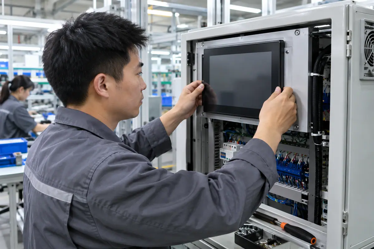
A convenient HDMI input does not remove cover, touch or mounting requirements. Evaluate image content at working light and angle through the complete stack. Also, required gloves or styluses need sensor-specific evidence. Inspect after fastening because frame loads can affect display appearance or edge input. A desktop test can prove an interface while leaving the equipment task unqualified. Keep optical and input acceptance distinct.
A familiar port can distract from unusable viewing or input. A module that works on a bench may fail required tasks inside the final bezel.
Which trial result changes the decision?
Test the finished operator task. Fit the assembly in the intended housing and use production content. Run named input tasks and inspect mounted optics, then close failures before treating cable convenience as product suitability.
- Working light
- Mounted optics
- Named input
- Edge access
| Decision point | Requirement to retain | Related check |
|---|---|---|
| Failure boundary | A familiar port can distract from unusable viewing or input. A module that works on a bench may fail required tasks inside the final bezel. | Named input |
| Approval action | Fit the assembly in the intended housing and use production content. Run named input tasks and inspect mounted optics, then close failures before treating cable convenience as product suitability. | Edge access |
Module quotes need a defined LCD, sensor and controller boundary. touch display module scope.
For example, an OEM terminal may show HDMI video correctly but send USB touch to a neighboring monitor. Check host display mapping before replacing the sensor. Then test reconnect and sleep to confirm the mapping persists. Review bridge identification and supported video modes separately if image geometry is also wrong. This hypothetical diagnosis shows why successful video output does not establish a complete touch-display connection.
9. How should board and firmware alternatives be reviewed?
A different bridge can change supported modes, identification and startup behavior. A touch board change can alter drivers or mapping. Meanwhile, an LCD substitution may require new output timing inside the receiver assembly. Keep every pairing and firmware reference controlled. Purchasing should not accept a visually similar board as equivalent. Review proposed differences and test the host behavior affected by them.
An alternative can show an image while losing sleep recovery or correct touch mapping. Silent firmware changes can invalidate previous acceptance evidence.
How can purchasing compare the evidence?
Requalify the receiver-panel combination. Request a board, LCD and firmware difference record for substitutions. Repeat supported modes, startup and touch trials, then approve alternatives only with applicable recorded compatibility results.
- Bridge reference
- Identification revision
- LCD output settings
- Touch configuration
| Decision point | Requirement to retain | Related check |
|---|---|---|
| Failure boundary | An alternative can show an image while losing sleep recovery or correct touch mapping. Silent firmware changes can invalidate previous acceptance evidence. | LCD output settings |
| Approval action | Request a board, LCD and firmware difference record for substitutions. Repeat supported modes, startup and touch trials, then approve alternatives only with applicable recorded compatibility results. | Touch configuration |
Review the capacitive product context if glass-front or gesture operation enters the specification. capacitive touchscreen options.
10. What should a released HDMI touch module preserve?
Release receiver-panel pairing, video modes, supply, cables and separate touch configuration. Include host settings, mapping and installed acceptance evidence. By contrast, HDMI touch display says little about the functions that passed. Keep service access and approved alternatives visible. A later host update or firmware change should trigger relevant review. Repeat supply should reproduce the accepted connection and operator task, not merely the same connector on a front photograph.
A generic product name can hide unsupported variants. Host or board changes may alter startup and input behavior despite unchanged outside geometry.
What should the team release next?
Release the tested host connection. Send a reconciled hardware, cable and software pack with the order. Agree on change notices and post-service checks, then validate affected modes before accepting receiver, LCD or host alternatives.
- Receiver-panel identity
- Supported modes
- Cable-power references
- Touch-host settings
Frequently asked questions about HDMI touch display module
Q1: Does an HDMI cable provide touch automatically? No. Identify and validate the actual supported touch connection and driver path.
Q2: Does an interface version guarantee every video mode? No. The receiver, bridge, LCD and source must support the required actual configuration.
Q3: Why can touch control another monitor? The host may map reports to the wrong display; verify supported display arrangements and transforms.
Q4: Can a replacement bridge be accepted by appearance? No. Review modes, panel pairing, identification, startup and firmware behavior.
Q5: What should the order identify? Receiver and LCD references, supported modes, power, cables, touch protocol and accepted host configuration.