
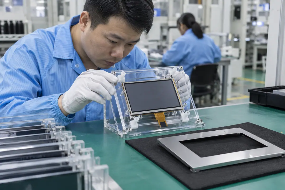
LCD and touch panel compatibility requires agreement across physical areas, optical layers, sensing electronics, host interfaces and software. Two working parts can still fail when joined, mounted or driven by a different host. This guide builds an interface-by-interface compatibility matrix and a controlled diagnostic path. It helps OEM engineers distinguish an alignment fault from wiring, timing, sensing or coordinate mapping. Purchasing can then request demonstrably equivalent combinations rather than assume that the same diagonal and connector make components interchangeable.
Contents: 1 · 2 · 3 · 4 · 5 · 6 · 7 · 8 · 9 · 10
1. Which compatibility boundary should be defined?
List the LCD, touch sensor, cover, joining, controller, host and enclosure. Each has interfaces that need a named owner. For example, a factory may qualify a joined stack while the OEM retains host software. Meanwhile, component datasheets do not automatically validate the finished combination. State what the compatibility decision includes and excludes. A boundary matrix prevents one successful bench function from being mistaken for complete product acceptance.
An undefined compatibility claim can hide untested mounting or software. Component evidence may be transferred to a system configuration it never covered.
Buyer checklist for LCD and touch panel compatibility
Define the combination being judged. Create an interface matrix with component references and responsibility owners. Mark supplier and OEM test boundaries, then use the same matrix for quotation, sample trial and failure closure.
- Component references
- Interface owners
- Supplier test boundary
- OEM test boundary
| Decision point | Requirement to retain | Related check |
|---|---|---|
| Failure boundary | An undefined compatibility claim can hide untested mounting or software. Component evidence may be transferred to a system configuration it never covered. | Supplier test boundary |
| Approval action | Create an interface matrix with component references and responsibility owners. Mark supplier and OEM test boundaries, then use the same matrix for quotation, sample trial and failure closure. | OEM test boundary |
A bonding proposal changes the assembled optical and mechanical interface; review its construction context. fully laminated touchscreen construction.
2. How should display, sensor and opening areas agree?
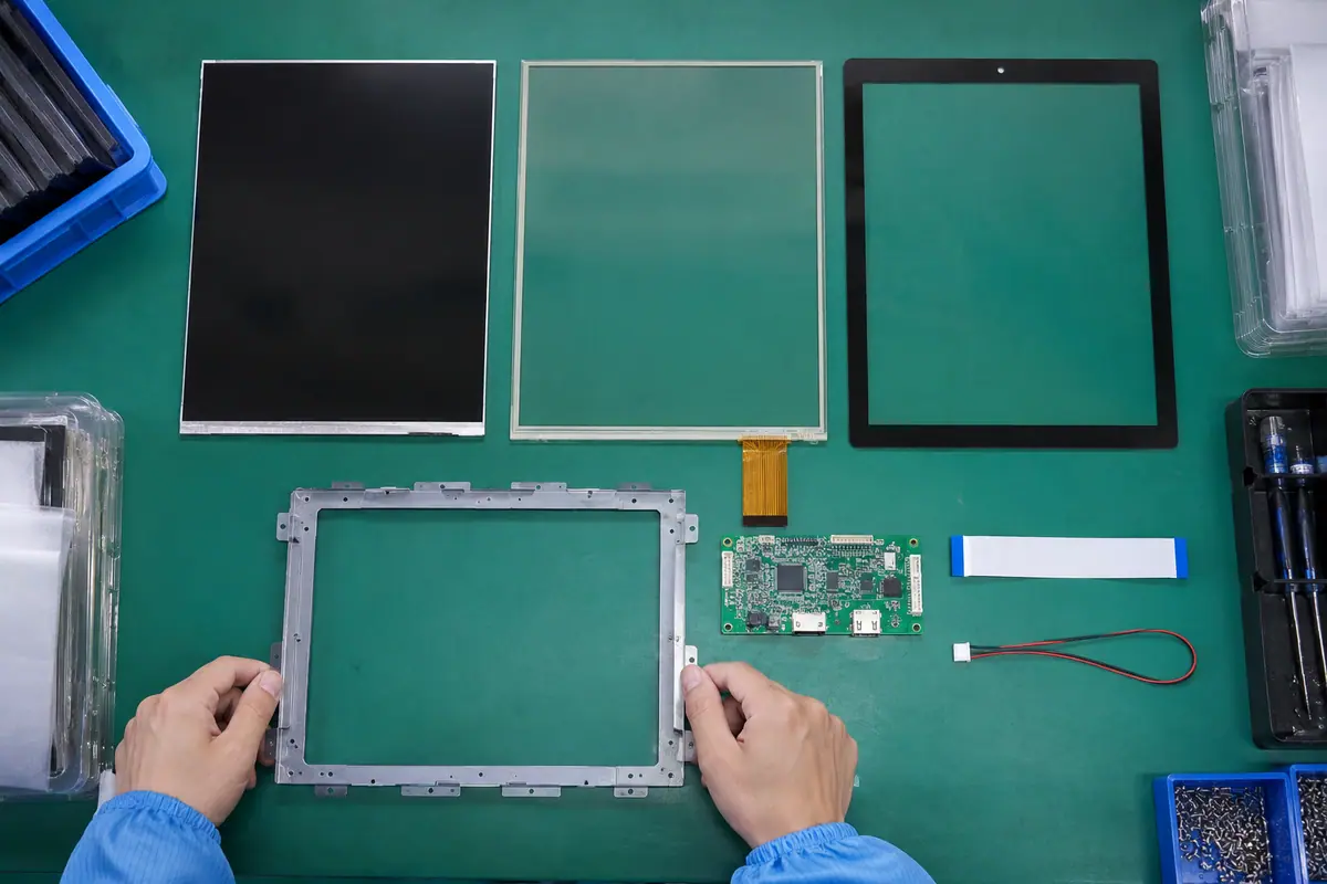
LCD active area, sensor usable area and front opening are separate. Outside component dimensions create another check. Also, tolerances can shift alignment and reduce usable margins. Compare drawings on common datums rather than matching diagonal alone. Required corner targets must remain both visible and reachable. Calibration can map coordinates but cannot create missing physical coverage. Inspect actual production-intent assemblies.
An apparently aligned center can conceal cropped edges. A sensor that fits outside dimensions may not cover required controls within its usable area.
Which evidence should accompany the sample?
Compare three areas on one drawing. Overlay controlled area drawings and tolerance limits. Verify front opening and required targets on fitted samples, then resolve physical coverage before changing software mapping or interface layout.
- LCD active area
- Sensor usable area
- Front opening
- Tolerance margins
| Decision point | Requirement to retain | Related check |
|---|---|---|
| Failure boundary | An apparently aligned center can conceal cropped edges. A sensor that fits outside dimensions may not cover required controls within its usable area. | Front opening |
| Approval action | Overlay controlled area drawings and tolerance limits. Verify front opening and required targets on fitted samples, then resolve physical coverage before changing software mapping or interface layout. | Tolerance margins |
For a machine installation, relate these checks to mounted-console and operator conditions. industrial control touchscreen context.
3. What thickness and support conditions affect compatibility?
The stack needs adequate depth, support and clearance for its selected sensor mechanism. A pressure membrane requires intended movement while glass and LCD need suitable mounting. Meanwhile, gasket and fastener loads can alter both functions. Include rear boards and tails in the envelope. A loose pair resting together cannot establish mounted compatibility. Review thermal movement where applicable using defined conditions and qualified owners.
A neat front fit can hide rear interference or edge preload. Software adjustments cannot correct physical LCD stress or blocked pressure-layer movement.
What should the test owner record?
Inspect compatibility after mounting. Approve a full cross-section with support and cable clearances. Inspect image, idle input and edge response after fastening, then correct mechanical conflicts before controller tuning or calibration.
- Stack depth
- Support points
- Edge clearance
- Rear envelope
| Decision point | Requirement to retain | Related check |
|---|---|---|
| Failure boundary | A neat front fit can hide rear interference or edge preload. Software adjustments cannot correct physical LCD stress or blocked pressure-layer movement. | Edge clearance |
| Approval action | Approve a full cross-section with support and cable clearances. Inspect image, idle input and edge response after fastening, then correct mechanical conflicts before controller tuning or calibration. | Rear envelope |
Healthcare equipment introduces device-specific cleaning and qualification questions; keep those outside generic component claims. medical touchscreen context.
Primary reference: ST embedded display and graphics overview. Verify its applicable scope against the proposed build.
4. How should optical joining and front materials be checked?
Cover, spacing, adhesive and LCD polarizer contribute to appearance and layer interaction. For example, a clear sensor alone can still add reflections after assembly. Also, joining can change mechanical load and capacitive conditions. Define material references, alignment and defect inspection. A bonding method suitable for one stack should not be presumed suitable for another architecture. Keep rework and cleaning boundaries visible in the compatibility review.
Unspecified materials can introduce haze, bubbles or touch changes. A visually similar adhesive substitution may invalidate prior joined-stack evidence.
Which installed detail needs approval?
Qualify the material between components. Request an approved layer drawing and joining references. Inspect complete optics and input after the actual process, then review material changes through both appearance and sensing acceptance.
- Front material
- Joining reference
- Alignment method
- Defect inspection
| Decision point | Requirement to retain | Related check |
|---|---|---|
| Failure boundary | Unspecified materials can introduce haze, bubbles or touch changes. A visually similar adhesive substitution may invalidate prior joined-stack evidence. | Alignment method |
| Approval action | Request an approved layer drawing and joining references. Inspect complete optics and input after the actual process, then review material changes through both appearance and sensing acceptance. | Defect inspection |
Compare the application boundary before assuming a single demonstration covers every installation. application solution overview.
5. What LCD video and power interfaces must match?
The host or supplied bridge must support panel timing, format, initialization and supplies. Connector count cannot establish those requirements. Meanwhile, backlight drive may be separate from LCD logic. Use exact references and applicable documentation before energizing a new pairing. A stable picture on another kit proves only that demonstrated configuration. Review cold boot and recovery on the intended source, not just an already-running image.
A same-size LCD can require different signals or startup. Incorrect power assignment can damage components rather than merely produce an incompatible image.
How can engineering close this check?
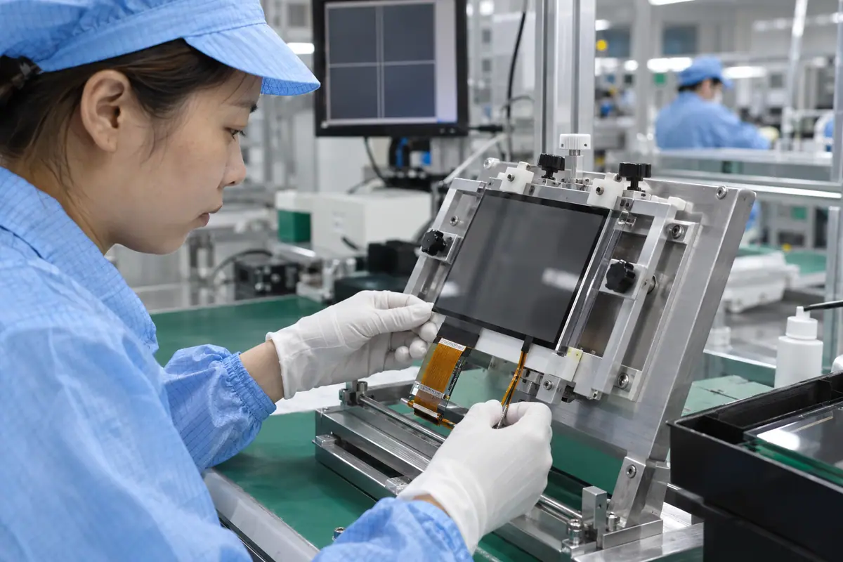
Match the documented video-power path. Compare host, bridge and LCD interface records with qualified electronics staff. Approve pin maps and supplies, then verify documented modes and startup before wider compatibility testing.
- Video timing
- Initialization
- Signal and supply map
- Backlight boundary
| Decision point | Requirement to retain | Related check |
|---|---|---|
| Failure boundary | A same-size LCD can require different signals or startup. Incorrect power assignment can damage components rather than merely produce an incompatible image. | Signal and supply map |
| Approval action | Compare host, bridge and LCD interface records with qualified electronics staff. Approve pin maps and supplies, then verify documented modes and startup before wider compatibility testing. | Backlight boundary |
Review public supplier information alongside evidence for the actual part being quoted. factory background.
6. Which sensor-controller relationship must be supported?
The touch controller must support the proposed sensor architecture and installed stack. Four-wire, five-wire and PCAP arrangements need different sensing paths. Also, configuration can depend on cover, LCD and enclosure. A compatible-looking tail does not establish a supported pairing. Check raw reports before application mapping. Keep production board and firmware identities visible. Component capability claims should be interpreted within their actual implementation and tested conditions.
A sensor can align mechanically yet remain electrically unsupported. A controller substitution may change signal range, features or host behavior.
What failure would reject this configuration?
Confirm a supported sensing pair. Obtain the sensor-controller pairing evidence and configuration references. Test raw input with the final display and mount, then review proposed alternatives before treating them as equivalent sensing assemblies.
- Sensor architecture
- Controller support
- Installed stack
- Raw report behavior
| Decision point | Requirement to retain | Related check |
|---|---|---|
| Failure boundary | A sensor can align mechanically yet remain electrically unsupported. A controller substitution may change signal range, features or host behavior. | Installed stack |
| Approval action | Obtain the sensor-controller pairing evidence and configuration references. Test raw input with the final display and mount, then review proposed alternatives before treating them as equivalent sensing assemblies. | Raw report behavior |
Send the controlled drawing and unresolved test questions with the sample configuration attached. technical inquiry route.
7. What host mapping can mimic incompatibility?
Video and touch often use different coordinate origins and scales. Rotation, offset and display assignment belong in controlled software. For example, correct raw points can select the wrong corner after a transform changes. Meanwhile, a multi-display host can direct touch elsewhere. Check raw and application events separately. Replacing a mechanically and electrically suitable panel will not repair an incorrect transform. Preserve mapping ownership through service updates.
Multiple transforms can apply scaling twice. Manual setup that is absent from release documentation can make replacement units look incompatible.
What should quality retain?
Trace input before replacing parts. Trace raw coordinates through each host transform. Test known targets after boot, rotation and reconnect, then freeze accepted mapping and display assignment with the module configuration.
- Raw coordinate scale
- Axis orientation
- Transform ownership
- Display assignment
| Decision point | Requirement to retain | Related check |
|---|---|---|
| Failure boundary | Multiple transforms can apply scaling twice. Manual setup that is absent from release documentation can make replacement units look incompatible. | Transform ownership |
| Approval action | Trace raw coordinates through each host transform. Test known targets after boot, rotation and reconnect, then freeze accepted mapping and display assignment with the module configuration. | Display assignment |
Module quotes need a defined LCD, sensor and controller boundary. touch display module scope.
8. Which operating conditions must the combined pair demonstrate?
Test required input objects, display states and exposures on the final host and enclosure. A dry finger result does not qualify gloves or moisture. Also, display activity and power changes can expose weak sensing conditions. Keep sealing and chemical compatibility separate where applicable. Define observable failures and recovery. The combined acceptance should reflect intended use rather than a generic list of impressive demonstrations or unrelated extreme tests.
A loose or quiet sample can hide installed edge and noise behavior. A successful wet tap does not prove enclosure protection or material compatibility.

Which trial result changes the decision?
Test the combined operating states. Create a condition matrix with task owners and limits. Log misses, unwanted events and recovery on fitted samples, then retest affected conditions after any stack or configuration change.
- Named input
- Display state
- Defined exposure
- Required recovery
| Decision point | Requirement to retain | Related check |
|---|---|---|
| Failure boundary | A loose or quiet sample can hide installed edge and noise behavior. A successful wet tap does not prove enclosure protection or material compatibility. | Defined exposure |
| Approval action | Create a condition matrix with task owners and limits. Log misses, unwanted events and recovery on fitted samples, then retest affected conditions after any stack or configuration change. | Required recovery |
Review the capacitive product context if glass-front or gesture operation enters the specification. capacitive touchscreen options.
For example, an OEM may combine a replacement LCD with its existing touch sensor and observe missed edge input. Confirm physical alignment and mounted support first. Then compare raw sensing while the new display operates relevant states. If raw input remains sound, inspect host mapping before replacing the sensor. After correction, retain the new paired references and regression results. This hypothetical compatibility review separates four possible fault boundaries without guessing from a matching diagonal.
9. How can the compatibility failure be located?
Start with the failed property: picture, raw touch, mapped input or mechanical appearance. Then inspect the relevant interface using applicable safe methods. Meanwhile, preserve original configuration and observations. A known-good compatible reference can help isolate a boundary but should not justify random substitutions. Change one relevant variable at a time where practical. Keep corrected settings and parts linked to the fault record so production can reproduce the solution.
Random replacement can conceal a host or mounting fault. A recovered demo with undocumented settings cannot establish a qualified repeatable combination.
How can purchasing compare the evidence?
Locate the failed interface methodically. Use an interface-based fault log and accountable test owners. Verify corrections against required tasks and modes, then update every affected drawing, component and software reference before acceptance.
- Failed property
- Original configuration
- Verified correction
- Affected-reference update
| Decision point | Requirement to retain | Related check |
|---|---|---|
| Failure boundary | Random replacement can conceal a host or mounting fault. A recovered demo with undocumented settings cannot establish a qualified repeatable combination. | Verified correction |
| Approval action | Use an interface-based fault log and accountable test owners. Verify corrections against required tasks and modes, then update every affected drawing, component and software reference before acceptance. | Affected-reference update |
Use the pressure-input product context when a suitable blunt stylus or glove is required. resistive touchscreen options.
10. What makes an alternative combination truly acceptable?
Approve alternatives against controlled interfaces and relevant test evidence. Matching size, front appearance or connector family is insufficient. Also, a changed LCD may need touch retests while a changed controller may need host review. Keep proposed and accepted alternatives separate. Release a reproducible component combination and its qualification boundaries. Purchasing should receive explicit references and change triggers rather than a broad interchangeable label.
An individually good substitute can fail beside an existing partner. Silent changes can invalidate acceptance without an obvious external difference.
What should the team release next?
Approve demonstrated interface equivalence. Request a difference matrix for proposed alternatives. Retest affected physical, optical, video and input conditions, then approve repeat supply only against reconciled references and applicable recorded evidence.
- Difference matrix
- Affected-interface tests
- Accepted references
- Change-review triggers
Frequently asked questions about LCD and touch panel compatibility
Q1: Does matching diagonal establish compatibility? No. Physical areas, depth, support, optics, electronics and software still need agreement.
Q2: Can calibration fix missing touch coverage? No. Mapping cannot create a usable physical area outside the sensor boundary.
Q3: Why can two good components fail together? Joining, mounting, electrical conditions or unsupported interfaces can change the combined behavior.
Q4: What distinguishes a mapping fault? Compare correct raw input with final application targets and inspect every coordinate transform.
Q5: What qualifies an alternative pair? Controlled interface differences and relevant fitted tests supporting the accepted complete configuration.