
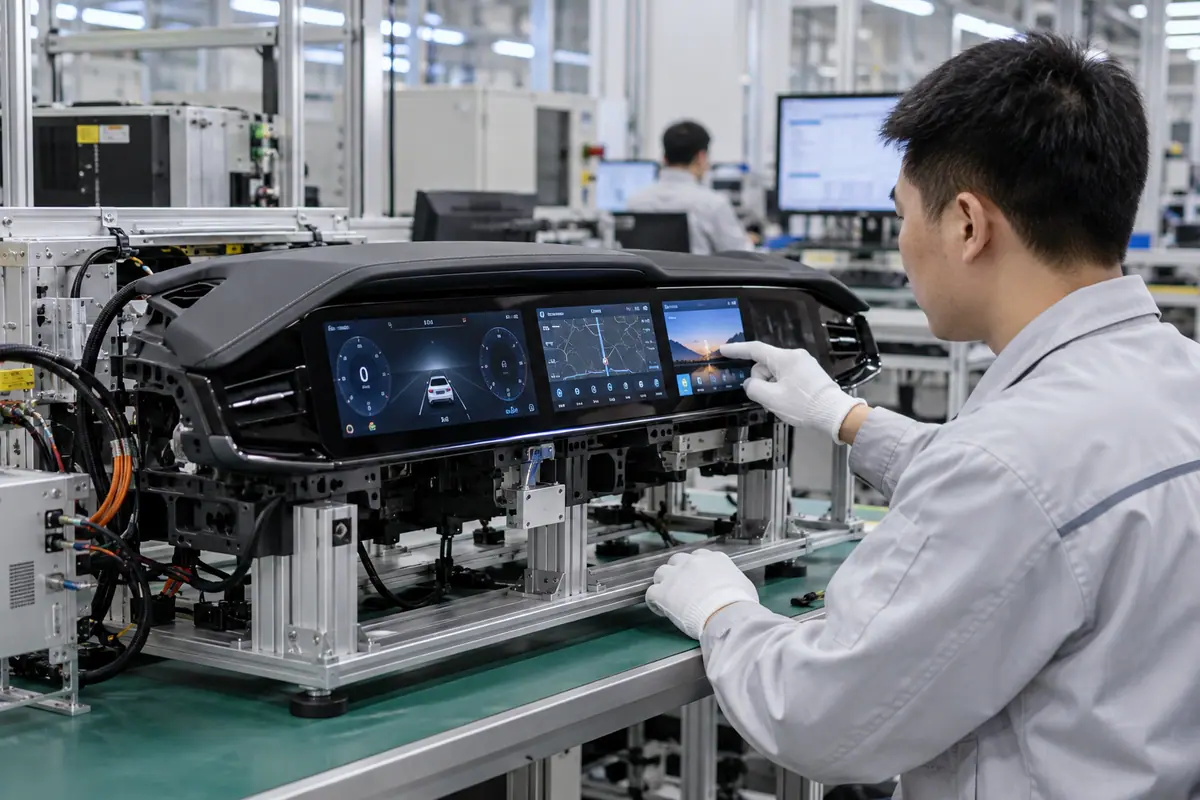
A fully laminated automotive display must be reviewed as an installed interface with a defined vehicle role. A bonded stack can change internal reflection and mechanical coupling, but it does not establish vehicle qualification. This guide separates optical, input, mounting, thermal and supply questions so engineers can request relevant sample evidence. Conduct interaction evaluations in a controlled stationary setup; any vehicle-level safety assessment belongs with the responsible automotive program.
Contents: 1 · 2 · 3 · 4 · 5 · 6 · 7 · 8 · 9 · 10
1. Where will the display operate in the vehicle?
Define the occupant, installation location and permitted tasks. A rear-seat interface differs from an instrument display. Also, the visible area, reach and viewing direction depend on the cabin geometry. Agree on the system boundary before selecting a front stack, and leave consequential interaction restrictions with the vehicle team.
A generic dashboard mockup may not represent the intended role. A visually convincing panel does not establish safe task allocation.
Buyer checklist for fully laminated automotive display
Define the vehicle role first. Record the installation and intended-use requirements with system owners. Evaluate representative tasks in a stationary fixture, then identify which questions require vehicle-level review before approving the component.
- Occupant position
- Display role
- Permitted tasks
- System owner
| Decision point | Requirement to retain | Related check |
|---|---|---|
| Failure boundary | A generic dashboard mockup may not represent the intended role. A visually convincing panel does not establish safe task allocation. | Permitted tasks |
| Approval action | Record the installation and intended-use requirements with system owners. Evaluate representative tasks in a stationary fixture, then identify which questions require vehicle-level review before approving the component. | System owner |
Use the pressure-input product context when a suitable blunt stylus or glove is required. resistive touchscreen options.
2. Which viewing conditions should the optical trial reproduce?
Cabin reflections depend on screen angle, nearby surfaces and light direction. Meanwhile, polarized eyewear can affect visible content depending on the display stack and viewing orientation. Compare required symbols and contrast on complete samples with equivalent settings. Do not judge the proposal only from a front-facing studio photograph.
Reduced internal reflection may coexist with strong front-surface glare. An unmatched brightness comparison can overstate a bonding benefit.

Which evidence should accompany the sample?
Reproduce the viewing geometry. Use a representative stationary mounting fixture and controlled light conditions. Record viewing positions and eyewear states where relevant, then retain observations of required content rather than only promotional photographs.
- Screen angle
- Incident light
- Required content
- Eyewear condition
| Decision point | Requirement to retain | Related check |
|---|---|---|
| Failure boundary | Reduced internal reflection may coexist with strong front-surface glare. An unmatched brightness comparison can overstate a bonding benefit. | Required content |
| Approval action | Use a representative stationary mounting fixture and controlled light conditions. Record viewing positions and eyewear states where relevant, then retain observations of required content rather than only promotional photographs. | Eyewear condition |
A bonding proposal changes the assembled optical and mechanical interface; review its construction context. fully laminated touchscreen construction.
3. How should solar and cabin heat be separated from optical claims?
Sunlight exposure can affect the thermal state of a display even when visibility improves. Adhesive, LCD, electronics and enclosure materials each have relevant limits. Also, power settings change heat generation. A clear picture at room conditions cannot establish performance after the installed assembly reaches its intended operating conditions.
A material limit is not automatically the complete-module limit. A bonded sample may still need changes to heat transfer or operating strategy.
What should the test owner record?
Evaluate the powered thermal assembly. Ask the thermal owner to define relevant conditions and acceptance criteria. Evaluate the powered mounted sample, then inspect image quality, input and bond appearance within the approved system test plan.
- Exposure conditions
- Power setting
- Heat path
- Functional limits
| Decision point | Requirement to retain | Related check |
|---|---|---|
| Failure boundary | A material limit is not automatically the complete-module limit. A bonded sample may still need changes to heat transfer or operating strategy. | Heat path |
| Approval action | Ask the thermal owner to define relevant conditions and acceptance criteria. Evaluate the powered mounted sample, then inspect image quality, input and bond appearance within the approved system test plan. | Functional limits |
For a machine installation, relate these checks to mounted-console and operator conditions. industrial control touchscreen context.
Primary reference: 3M optically clear adhesive application context. Verify its applicable scope against the proposed build.
4. What mounting loads reach the bonded stack?
Frame support, adhesive joints and fastener preload determine how the module is constrained. Meanwhile, differential movement among materials can change stress. Review tolerances, support points and clearances before assigning strength benefits to optical joining. The front stack should not be used to compensate for an undefined bracket or housing load path.
A stiff mounting scheme can introduce display distortion or edge damage. A bond label cannot identify the weakest installed interface.
Which installed detail needs approval?
Follow the installed load path. Approve the mounting section and assembly method with mechanical owners. Inspect fitted optics and input, then trace proposed loads through the complete assembly before accepting the mounting design.
- Bracket support
- Fastener preload
- Clearance stack
- Material movement
| Decision point | Requirement to retain | Related check |
|---|---|---|
| Failure boundary | A stiff mounting scheme can introduce display distortion or edge damage. A bond label cannot identify the weakest installed interface. | Clearance stack |
| Approval action | Approve the mounting section and assembly method with mechanical owners. Inspect fitted optics and input, then trace proposed loads through the complete assembly before accepting the mounting design. | Material movement |
Healthcare equipment introduces device-specific cleaning and qualification questions; keep those outside generic component claims. medical touchscreen context.
5. How should vibration testing include the rest of the module?
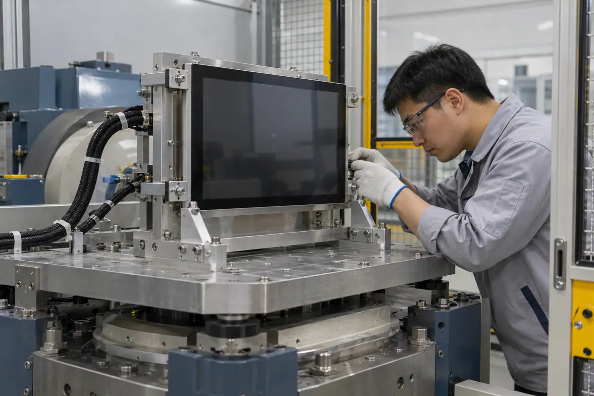
Boards, connectors and flexible tails remain part of the assembly. Also, powered functional monitoring can reveal faults absent from a post-test photograph. Select the required test method and conditions through the automotive program. Optical coupling should be treated as one design element, not as a substitute for installed mechanical qualification.
A loose connector may fail before the optical interface. A component-only report can exclude the actual bracket and cable route.
How can engineering close this check?
Monitor the complete assembly. Define sample mounting, routing and functional failure limits before testing. Retain pre-test and post-test inspections and event evidence, then investigate the failing interface rather than assuming every interruption is delamination.
- Test fixture
- Cable retention
- Functional events
- Post-test inspection
| Decision point | Requirement to retain | Related check |
|---|---|---|
| Failure boundary | A loose connector may fail before the optical interface. A component-only report can exclude the actual bracket and cable route. | Functional events |
| Approval action | Define sample mounting, routing and functional failure limits before testing. Retain pre-test and post-test inspections and event evidence, then investigate the failing interface rather than assuming every interruption is delamination. | Post-test inspection |
Compare the application boundary before assuming a single demonstration covers every installation. application solution overview.
6. Which input and electrical states need review?
Cover thickness, sensor geometry, controller configuration and nearby electronics influence touch operation. Meanwhile, host initialization and communication affect visible response. Include relevant supply and display states in a stationary evaluation. If gloves or moisture are intended conditions, define them explicitly instead of relying on a general automotive touchscreen description.
A quiet laboratory supply can hide installed interference. A host delay can be mistaken for a front-stack sensing failure.
What failure would reject this configuration?
Test the installed input path. Use the intended host, grounding and cable route. Log relevant touch and host behavior during required tasks, then repeat affected conditions after changes to the stack or controller configuration.
- Supply state
- Grounding scheme
- Host response
- Input conditions
| Decision point | Requirement to retain | Related check |
|---|---|---|
| Failure boundary | A quiet laboratory supply can hide installed interference. A host delay can be mistaken for a front-stack sensing failure. | Host response |
| Approval action | Use the intended host, grounding and cable route. Log relevant touch and host behavior during required tasks, then repeat affected conditions after changes to the stack or controller configuration. | Input conditions |
Review public supplier information alongside evidence for the actual part being quoted. factory background.
7. What environmental boundaries remain separate?
Condensation, humidity exposure, cleaning, surface wear and enclosure protection require defined methods and limits. Also, a cosmetic border and a structural perimeter seal serve different functions. The optical adhesive may occupy a gap without providing every environmental barrier the vehicle assembly needs. Keep each claimed protection tied to applicable evidence.
A clear initial bond can conceal an unqualified edge interface. A supplier term may imply a protection scope that the quote does not include.
What should quality retain?
Define each protection boundary. List relevant environmental requirements with their responsible owners. Request evidence for the proposed configuration, then identify remaining assembly-level tests and avoid transferring unrelated material claims into the vehicle specification.
- Edge design
- Cleaning exposure
- Humidity plan
- Claim scope
| Decision point | Requirement to retain | Related check |
|---|---|---|
| Failure boundary | A clear initial bond can conceal an unqualified edge interface. A supplier term may imply a protection scope that the quote does not include. | Humidity plan |
| Approval action | List relevant environmental requirements with their responsible owners. Request evidence for the proposed configuration, then identify remaining assembly-level tests and avoid transferring unrelated material claims into the vehicle specification. | Claim scope |
Send the controlled drawing and unresolved test questions with the sample configuration attached. technical inquiry route.
8. How should service and diagnostics be planned?
Decide whether the service organization replaces the joined module or an approved higher assembly. Access, connectors and software compatibility matter as much as front appearance. Meanwhile, specialist bond rework may be outside the field repair route. Define diagnostic checks that separate host, controller and optical faults before a replacement is ordered.
An interchangeable connector may conceal a different configuration. Uncontrolled separation can damage parts and invalidate prior inspection evidence.

Which trial result changes the decision?
Make the spare boundary explicit. Release spare identities and a diagnostic decision path. Demonstrate replacement in the stationary installation, then verify communication, mapping, image quality and relevant vehicle-program recovery checks after reassembly.
- Diagnostic route
- Replacement scope
- Configuration match
- Recovery verification
| Decision point | Requirement to retain | Related check |
|---|---|---|
| Failure boundary | An interchangeable connector may conceal a different configuration. Uncontrolled separation can damage parts and invalidate prior inspection evidence. | Configuration match |
| Approval action | Release spare identities and a diagnostic decision path. Demonstrate replacement in the stationary installation, then verify communication, mapping, image quality and relevant vehicle-program recovery checks after reassembly. | Recovery verification |
Module quotes need a defined LCD, sensor and controller boundary. touch display module scope.
For example, a stationary cabin fixture may show improved daytime readability while exposing a reflection at one passenger viewing angle. Changing the bracket angle could improve that task but alter clearances and mechanical loading. Review the consequences with the relevant owners and retest the installed sample. This hypothetical review does not establish a vehicle approval or a safe driving interaction.
9. Which factory records support an automotive program?
Ask for traceable material, process and inspection references for the quoted stack. Qualification claims should name the sample and method. Also, distinguish supplier capability evidence from a production part's approval status. Purchasing needs clear change ownership, especially when LCDs or cover parts are supplied by another party.
General industry experience does not prove that the proposed assembly is qualified. Missing lot links can obstruct an investigation after a pilot failure.
How can purchasing compare the evidence?
Request part-specific evidence. Align the RFQ with program-specific deliverables and exclusions. Review pilot records against the actual configuration, then close evidence gaps before committing to repeat production or making vehicle-qualification claims.
- Material records
- Process revision
- Inspection scope
- Program exclusions
| Decision point | Requirement to retain | Related check |
|---|---|---|
| Failure boundary | General industry experience does not prove that the proposed assembly is qualified. Missing lot links can obstruct an investigation after a pilot failure. | Inspection scope |
| Approval action | Align the RFQ with program-specific deliverables and exclusions. Review pilot records against the actual configuration, then close evidence gaps before committing to repeat production or making vehicle-qualification claims. | Program exclusions |
Review the capacitive product context if glass-front or gesture operation enters the specification. capacitive touchscreen options.
10. What defines the production-intent release?
Freeze the accepted stack, bracket, host and environmental requirements together. Preserve permitted-use and service constraints. By contrast, fully laminated automotive display alone does not define an equivalent replacement. Changes to adhesives, cover coatings, controllers or mounting should receive the relevant technical and program review before the revised part is accepted.
A narrow factory change notice can miss a customer-side mounting change. An unreviewed variant can invalidate previous test conclusions.
What should the team release next?
Release the installed configuration. Reference the accepted configuration in the order and change process. Require clear notices and responsibility boundaries, then repeat affected optical, mechanical, electrical and system checks before releasing substitutions.
- Stack identity
- Mounting reference
- Host revision
- Change approval
Frequently asked questions about fully laminated automotive display
Q1: Does lamination establish automotive qualification? No. Request part-specific evidence and follow the responsible vehicle program's qualification process.
Q2: Should the comparison include the cabin angle? Yes. Viewing geometry and surrounding reflections can change the usefulness of the optical result.
Q3: Can an adhesive datasheet qualify the whole display? No. The mounted stack, electronics, cables and operating conditions need relevant evaluation.
Q4: Where should touch tasks be evaluated? Use a controlled stationary fixture; vehicle-level use restrictions remain with the responsible program.
Q5: What should a spare preserve? The approved mechanical, electrical, optical and software configuration with defined recovery checks.