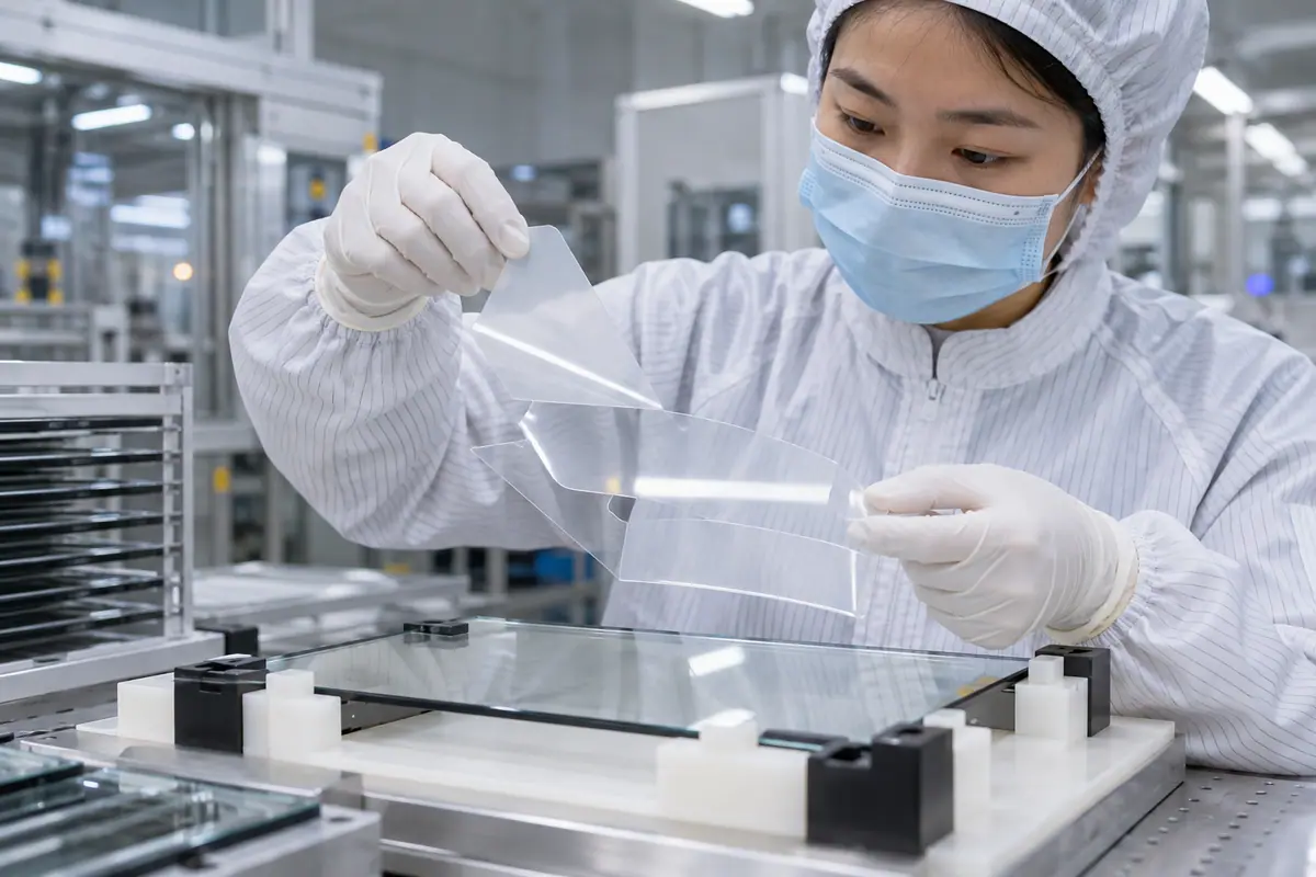
OCA optical bonding commonly refers here to joining with an optically clear adhesive film, rather than dispensing a liquid optical adhesive. Confirm that terminology with the supplier because OCA can also be used more broadly. A film's form does not eliminate the need for material selection, surface preparation, alignment and inspection. This guide follows a film-based route and identifies the evidence an OEM should request without inventing a universal lamination recipe.
Contents: 1 · 2 · 3 · 4 · 5 · 6 · 7 · 8 · 9 · 10
1. What does OCA mean in the proposed quote?
Confirm the exact film product, adhesive construction and joined interfaces. Also, distinguish the adhesive from release liners removed during processing. Terminology varies, so the acronym should lead to a material reference and cross-section. A film description alone does not identify thickness, surface compatibility or the process required for a particular display stack.
A broad OCA label can conceal a different material form. An unidentified liner can be mistaken for part of the finished stack.
Buyer checklist for OCA optical bonding
Identify the film construction. Request the material reference and layer section with supplied scope. Clarify the supplier's terminology, then compare proposals using actual products and interfaces instead of assuming the acronym defines an equivalent construction.
- Material product
- Finished layers
- Release liners
- Joined interfaces
| Decision point | Requirement to retain | Related check |
|---|---|---|
| Failure boundary | A broad OCA label can conceal a different material form. An unidentified liner can be mistaken for part of the finished stack. | Release liners |
| Approval action | Request the material reference and layer section with supplied scope. Clarify the supplier's terminology, then compare proposals using actual products and interfaces instead of assuming the acronym defines an equivalent construction. | Joined interfaces |
Send the controlled drawing and unresolved test questions with the sample configuration attached. technical inquiry route.
2. How should film thickness be selected?
Thickness must suit geometry, surface features and the required stack. Meanwhile, printed borders or local steps can change contact conditions. Material guidance and trial evidence should support the proposed choice. Avoid treating a thicker film as automatically better or transferring a successful construction from a different screen without reviewing its interfaces.
A nominal thickness can hide an unsuitable local contact condition. An arbitrary change may affect fit, optics and the touch configuration.
Which evidence should accompany the sample?
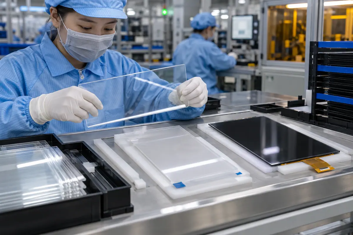
Match thickness to geometry. Provide surface and stack geometry to the process owner. Review the proposed thickness against applicable material guidance, then verify appearance, dimensions and relevant input behavior on the identified complete sample.
- Surface profile
- Border step
- Stack dimension
- Sample evidence
| Decision point | Requirement to retain | Related check |
|---|---|---|
| Failure boundary | A nominal thickness can hide an unsuitable local contact condition. An arbitrary change may affect fit, optics and the touch configuration. | Stack dimension |
| Approval action | Provide surface and stack geometry to the process owner. Review the proposed thickness against applicable material guidance, then verify appearance, dimensions and relevant input behavior on the identified complete sample. | Sample evidence |
Module quotes need a defined LCD, sensor and controller boundary. touch display module scope.
3. What starts before liner removal?
Review incoming surface condition, approved cleaning and part protection. Film handling introduces its own contamination opportunities when adhesive surfaces become exposed. Also, storage and preparation should follow the relevant product guidance. The supplier needs a defined sequence that limits particles and handling marks while preserving coatings and fragile display surfaces.
Contamination can become trapped at an otherwise suitable interface. An incompatible cleaner can damage a part before lamination begins.
What should the test owner record?
Protect exposed optical surfaces. Ask for the applicable preparation and handling sequence with inspection responsibility. Observe representative parts and retain approved exceptions, then investigate pilot defects using the actual process record rather than attributing all problems to film choice.
- Incoming inspection
- Cleaning method
- Liner sequence
- Handling protection
| Decision point | Requirement to retain | Related check |
|---|---|---|
| Failure boundary | Contamination can become trapped at an otherwise suitable interface. An incompatible cleaner can damage a part before lamination begins. | Liner sequence |
| Approval action | Ask for the applicable preparation and handling sequence with inspection responsibility. Observe representative parts and retain approved exceptions, then investigate pilot defects using the actual process record rather than attributing all problems to film choice. | Handling protection |
Review the capacitive product context if glass-front or gesture operation enters the specification. capacitive touchscreen options.
Primary reference: 3M optically clear adhesive application context. Verify its applicable scope against the proposed build.
4. How does the cut shape affect joining?
The film outline and openings should fit the joining region, borders and exclusions. Meanwhile, registration to the cover and display must preserve the intended visible area. Different part revisions can require different conversion tooling or setup. Treat film shape as a controlled geometry rather than a generic sheet that can be adjusted informally during production.
An incorrect outline can expose adhesive or leave an intended area unsupported. An outdated cut pattern can create repeated alignment defects.
Which installed detail needs approval?
Control the converted shape. Link the converted film shape and setup to the controlled drawing. Review relevant edges and openings on the sample, then require change review before accepting geometry or tooling revisions that affect the optical interface.
- Film outline
- Required openings
- Registration datum
- Tooling revision
| Decision point | Requirement to retain | Related check |
|---|---|---|
| Failure boundary | An incorrect outline can expose adhesive or leave an intended area unsupported. An outdated cut pattern can create repeated alignment defects. | Registration datum |
| Approval action | Link the converted film shape and setup to the controlled drawing. Review relevant edges and openings on the sample, then require change review before accepting geometry or tooling revisions that affect the optical interface. | Tooling revision |
Use the pressure-input product context when a suitable blunt stylus or glove is required. resistive touchscreen options.
5. What does wetting mean for a film route?
In a suitable pressure-sensitive film construction, wetting refers to the adhesive establishing contact with the mating surface. Conditions depend on the exact material and parts. Also, local features can complicate contact. This is not permission to apply an invented pressure or temperature schedule; qualified process owners must establish a compatible route.
Incomplete contact can appear as optical nonuniformity or voids. Excessive or unsuitable processing can damage components while attempting to improve contact.

How can engineering close this check?
Verify contact without guessing settings. Request the material-specific process rationale and critical output checks. Verify contact appearance and component function on representative builds, then document the accepted route and its limits rather than prescribing unsupported universal settings.
- Material guidance
- Surface contact
- Component limits
- Output inspection
| Decision point | Requirement to retain | Related check |
|---|---|---|
| Failure boundary | Incomplete contact can appear as optical nonuniformity or voids. Excessive or unsuitable processing can damage components while attempting to improve contact. | Component limits |
| Approval action | Request the material-specific process rationale and critical output checks. Verify contact appearance and component function on representative builds, then document the accepted route and its limits rather than prescribing unsupported universal settings. | Output inspection |
A bonding proposal changes the assembled optical and mechanical interface; review its construction context. fully laminated touchscreen construction.
6. How should trapped-air or void concerns be reviewed?
Discuss the proposed contact sequence and any qualified de-airing steps with the process owner. A route used for one film and geometry may not suit another. Meanwhile, the inspection method should distinguish visible defects and their acceptance limits. Do not promise that every film assembly can become void-free through an additional generic processing step.
A late rescue step may not correct contamination or bad geometry. Repeated processing can introduce new component or surface damage.
What failure would reject this configuration?
Trace the source of a void. Define relevant void and particle limits before the pilot. Review failures against handling, alignment and contact records, then approve corrective processing only when the actual material and component constraints support it.
- Contact sequence
- Defect method
- Failure records
- Corrective limits
| Decision point | Requirement to retain | Related check |
|---|---|---|
| Failure boundary | A late rescue step may not correct contamination or bad geometry. Repeated processing can introduce new component or surface damage. | Failure records |
| Approval action | Define relevant void and particle limits before the pilot. Review failures against handling, alignment and contact records, then approve corrective processing only when the actual material and component constraints support it. | Corrective limits |
For a machine installation, relate these checks to mounted-console and operator conditions. industrial control touchscreen context.
7. What should optical and touch acceptance cover?
Inspect the joined viewing area under controlled conditions and verify the complete input path. Film thickness and front-stack changes should remain linked to controller and host references. Also, display artifacts may arise from mechanical stress rather than an adhesive optical property. Separate these findings so corrective actions address the observed cause.
A visually clear film bond can still accompany poor edge input. A controller adjustment may conceal a mounting issue without resolving it.
What should quality retain?
Test the complete film-bonded stack. Retain identified sample settings and inspection conditions. Evaluate required tasks after mounting, then investigate optical, mechanical and input failures separately before accepting material changes or configuration tuning as the remedy.
- Optical setup
- Mounting stress
- Controller revision
- Required input
| Decision point | Requirement to retain | Related check |
|---|---|---|
| Failure boundary | A visually clear film bond can still accompany poor edge input. A controller adjustment may conceal a mounting issue without resolving it. | Controller revision |
| Approval action | Retain identified sample settings and inspection conditions. Evaluate required tasks after mounting, then investigate optical, mechanical and input failures separately before accepting material changes or configuration tuning as the remedy. | Required input |
Healthcare equipment introduces device-specific cleaning and qualification questions; keep those outside generic component claims. medical touchscreen context.
8. How should film rework be evaluated?
Separation outcome depends on the actual film, surfaces and approved recovery method. Some parts may be lost or require renewed inspection. Meanwhile, residue removal can create additional risk for coatings and display surfaces. Ask for the qualified rework boundary rather than assuming that dry film means simple or harmless separation.
An unapproved removal attempt can turn a cosmetic reject into component loss. A cleaned surface may no longer match the original accepted condition.

Which trial result changes the decision?
Define a qualified recovery boundary. Define authorized rework, part-loss ownership and reinspection requirements. Compare the demonstrated recovery route with complete-module replacement, then retain records linking repaired parts to any changed materials or process conditions.
- Separation method
- Residue control
- Part-loss owner
- Reinspection scope
| Decision point | Requirement to retain | Related check |
|---|---|---|
| Failure boundary | An unapproved removal attempt can turn a cosmetic reject into component loss. A cleaned surface may no longer match the original accepted condition. | Part-loss owner |
| Approval action | Define authorized rework, part-loss ownership and reinspection requirements. Compare the demonstrated recovery route with complete-module replacement, then retain records linking repaired parts to any changed materials or process conditions. | Reinspection scope |
Compare the application boundary before assuming a single demonstration covers every installation. application solution overview.
For example, a film-bonded sample might show a visible feature near a printed border while the central area looks clear. Review the actual border geometry, film choice, handling and contact route before changing processing conditions. Repeat inspection using the agreed method on a controlled corrective build. This hypothetical investigation does not prescribe a material or processing recipe.
9. What makes film-based quotations comparable?
Normalize exact material, converted shape, setup, inspection and accepted output scope. Also, customer-owned components and reject terms affect exposure. A film route may shift work into conversion tooling or handling rather than liquid dispensing. Compare the complete offer with its assumptions instead of declaring a universal cost advantage from material form.
A low material price can exclude conversion or inspection. Different reject terms can outweigh a nominal per-unit fee difference.
How can purchasing compare the evidence?
Compare the complete film route. Use one RFQ scope and responsibility matrix for all offers. Ask suppliers to identify tooling and change costs, then reconcile pilot evidence and accepted-output ownership before comparing repeat-production pricing.
- Film identity
- Conversion tooling
- Inspection inclusion
- Reject ownership
| Decision point | Requirement to retain | Related check |
|---|---|---|
| Failure boundary | A low material price can exclude conversion or inspection. Different reject terms can outweigh a nominal per-unit fee difference. | Inspection inclusion |
| Approval action | Use one RFQ scope and responsibility matrix for all offers. Ask suppliers to identify tooling and change costs, then reconcile pilot evidence and accepted-output ownership before comparing repeat-production pricing. | Reject ownership |
Review public supplier information alongside evidence for the actual part being quoted. factory background.
10. What should the OCA release preserve?
Freeze the exact film, converted geometry, joining surfaces and accepted process references. Include inspection and host configuration links. By contrast, OCA optical bonding does not identify one universal construction. Changes to liner handling, surface preparation, film shape or stack materials may require relevant checks even when the adhesive supplier remains unchanged.
A same-brand substitution can still change the construction. An informal shape revision can invalidate the accepted alignment and edge appearance.
What should the team release next?
Release the identified film route. Release controlled material, drawing and process references with the order. Require specific change notices, then repeat affected optical, dimensional, input and service checks before approving substitutions or revised film geometry.
- Material identity
- Shape revision
- Process reference
- Change triggers
Frequently asked questions about OCA optical bonding
Q1: Does OCA always mean a dry film? Terminology can vary; this guide uses film-based OCA and requires the supplier to identify the exact product and form.
Q2: Is a thicker film automatically better? No. Select against geometry, material guidance, stack constraints and representative sample evidence.
Q3: Can one lamination recipe suit every film? No. Qualified process owners must account for the exact material, surfaces and component limits.
Q4: Does film construction guarantee easy rework? No. Request a qualified separation route, loss ownership and reinspection requirements.
Q5: What belongs in a film release record? Exact material, converted shape, joined surfaces, process and inspection references with relevant configuration links.