

A fully laminated industrial display should solve defined operator and installation problems, not merely provide a modern front appearance. Machine vibration, electrical loads, gloves, cleaning and service access create different acceptance questions. This guide focuses on the installed console and maintenance workflow. It does not infer an ingress, impact or safety rating from optical joining. Engineering and purchasing can use its task matrix to request a production-intent module and a comparable factory responsibility boundary.
Contents: 1 · 2 · 3 · 4 · 5 · 6 · 7 · 8 · 9 · 10
1. Which machine task requires the display?
List production, setup and fault-recovery interactions separately. A large status button differs from a gloved numeric entry task. Meanwhile, the console position determines reach and viewing angle. Keep safety-related controls with the system risk owner rather than assuming a touchscreen provides a machine safety architecture.
An attractive demonstration can hide small required controls or awkward operator posture. A sensor label cannot qualify consequential commands.
Buyer checklist for fully laminated industrial display
Start at the operator station. Observe representative tasks and write input and viewing requirements with their owners. Define mandatory gates, then evaluate laminated candidates using the actual operating interface rather than unrelated demo content.
- Production task
- Setup entry
- Recovery task
- Control boundary
| Decision point | Requirement to retain | Related check |
|---|---|---|
| Failure boundary | An attractive demonstration can hide small required controls or awkward operator posture. A sensor label cannot qualify consequential commands. | Recovery task |
| Approval action | Observe representative tasks and write input and viewing requirements with their owners. Define mandatory gates, then evaluate laminated candidates using the actual operating interface rather than unrelated demo content. | Control boundary |
Module quotes need a defined LCD, sensor and controller boundary. touch display module scope.
2. What visual problem should lamination address?
Compare required content under actual factory light and viewing positions. Suitable optical joining can reduce reflection at its addressed interface, but lighting and surface finish remain relevant. Also, fixed and moving operator positions create different visibility needs. A bright laboratory picture may not reproduce overhead-light reflections at a mounted console.
Different brightness settings can distort the comparison. A bonded front does not automatically establish readable content in the installation.

Which evidence should accompany the sample?
Test the installed viewing task. Record baseline glare and useful viewing conditions. Compare complete samples at equivalent settings, then accept a visual improvement only where the operator can reliably read required information.
- Ambient lighting
- Operator position
- Required symbols
- Useful brightness
| Decision point | Requirement to retain | Related check |
|---|---|---|
| Failure boundary | Different brightness settings can distort the comparison. A bonded front does not automatically establish readable content in the installation. | Required symbols |
| Approval action | Record baseline glare and useful viewing conditions. Compare complete samples at equivalent settings, then accept a visual improvement only where the operator can reliably read required information. | Useful brightness |
Review the capacitive product context if glass-front or gesture operation enters the specification. capacitive touchscreen options.
3. How should glove operation be tested?
Specify approved glove construction and fit, not only thickness. PCAP glove behavior depends on the assembled sensor, cover and controller. Meanwhile, pressure-based input needs suitable force transfer and a compatible construction. Test repeated entry, drags and release near required controls. Lamination alone does not establish glove compatibility.
A thin evaluation glove can hide a required thick-glove failure. Stronger sensitivity may alter unwanted input in another operating state.
What should the test owner record?
Use the shop-floor glove. Use named glove samples and the final module configuration. Observe retries and idle events, then repeat relevant dry, damp and bare-input states after any tuning or front-stack change.
- Glove identity
- Target layout
- Release behavior
- Configuration revision
| Decision point | Requirement to retain | Related check |
|---|---|---|
| Failure boundary | A thin evaluation glove can hide a required thick-glove failure. Stronger sensitivity may alter unwanted input in another operating state. | Release behavior |
| Approval action | Use named glove samples and the final module configuration. Observe retries and idle events, then repeat relevant dry, damp and bare-input states after any tuning or front-stack change. | Configuration revision |
Use the pressure-input product context when a suitable blunt stylus or glove is required. resistive touchscreen options.
Primary reference: 3M optically clear adhesive application context. Verify its applicable scope against the proposed build.
4. What mounting loads can change the result?
The metal console, gasket and fasteners determine how loads reach the joined stack. Also, rear brackets can interfere with boards or tails. Inspect after fastening rather than approving a loose sample. A stiff front can still transmit inappropriate stress into the LCD. Keep ground contacts deliberate and documented.
Overtightening can distort the image or edge input. An improvised rear support may create a failure absent on the bench.
Which installed detail needs approval?
Include the complete console mount. Approve the support cross-section and assembly method with mechanical staff. Test fitted optics and input, then correct interference and preload before changing controller settings to conceal physical problems.
- Gasket load
- Support points
- Rear clearance
- Ground contact
| Decision point | Requirement to retain | Related check |
|---|---|---|
| Failure boundary | Overtightening can distort the image or edge input. An improvised rear support may create a failure absent on the bench. | Rear clearance |
| Approval action | Approve the support cross-section and assembly method with mechanical staff. Test fitted optics and input, then correct interference and preload before changing controller settings to conceal physical problems. | Ground contact |
A bonding proposal changes the assembled optical and mechanical interface; review its construction context. fully laminated touchscreen construction.
5. Which electrical states belong in testing?
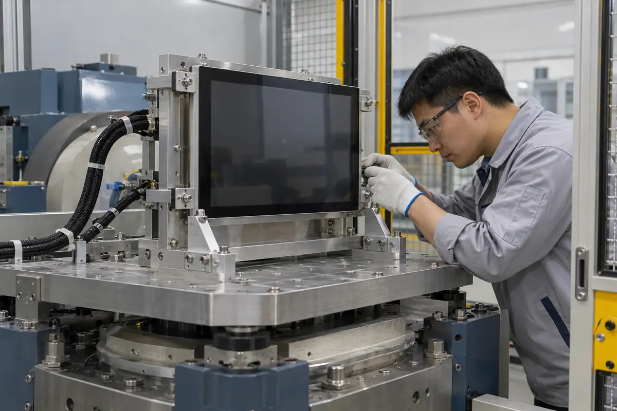
Motors, drives and switching supplies can change the sensing environment. Meanwhile, LCD activity and backlight settings add their own states. Use the intended supply and cable route. Log raw touch events separately from visible artifacts so a host or power fault does not automatically become a bonding defect.
Quiet idle tests can miss machine-state interference. A temporary laboratory supply can hide the installed electrical condition.
How can engineering close this check?
Operate the surrounding equipment. List relevant equipment and display states with the electronics owner. Run required input tasks while those states occur, then retain event logs and verified grounding and routing with the accepted configuration.
- Drive state
- Supply condition
- Display activity
- Cable routing
| Decision point | Requirement to retain | Related check |
|---|---|---|
| Failure boundary | Quiet idle tests can miss machine-state interference. A temporary laboratory supply can hide the installed electrical condition. | Display activity |
| Approval action | List relevant equipment and display states with the electronics owner. Run required input tasks while those states occur, then retain event logs and verified grounding and routing with the accepted configuration. | Cable routing |
For a machine installation, relate these checks to mounted-console and operator conditions. industrial control touchscreen context.
6. What cleaning and contamination must the front tolerate?
Cleaning agents, wipes and surface residue affect coatings, printing, adhesives and seals. Also, wiping a powered screen can generate input. Define whether operation continues during cleaning. A flush laminated front may ease access without proving chemical compatibility or enclosure protection. Keep those acceptance questions separate from visible clarity.
An unreviewed cleaner can damage surfaces or edges. A successful wipe demonstration does not establish repeated-exposure compatibility.
What failure would reject this configuration?
Write the maintenance procedure. Specify cleaner concentration, wipe material and powered state with maintenance owners. Request applicable material evidence, then inspect appearance, edge condition and input recovery after the approved cleaning trial.
- Cleaner identity
- Wipe method
- Powered state
- Recovery check
| Decision point | Requirement to retain | Related check |
|---|---|---|
| Failure boundary | An unreviewed cleaner can damage surfaces or edges. A successful wipe demonstration does not establish repeated-exposure compatibility. | Powered state |
| Approval action | Specify cleaner concentration, wipe material and powered state with maintenance owners. Request applicable material evidence, then inspect appearance, edge condition and input recovery after the approved cleaning trial. | Recovery check |
Healthcare equipment introduces device-specific cleaning and qualification questions; keep those outside generic component claims. medical touchscreen context.
7. How should vibration and cable movement be reviewed?
The adhesive is only one element of a moving assembly. Frame support, board retention, connectors and tail strain also matter. Meanwhile, test conditions must reflect the equipment requirement and applicable method. A joined front does not make unsupported electronics vibration-resistant. Inspect functional behavior and physical interfaces before and after relevant exposure.
A cable can fail before the optical bond. An unrelated component test cannot qualify the mounted console.
What should quality retain?
Follow the load into the interconnect. Define the fitted configuration and functional failure limits with qualified owners. Validate relevant mechanical exposure and communication, then retain support, fastener and routing references alongside the optical assembly record.
- Frame support
- Board retention
- Tail strain
- Functional monitoring
| Decision point | Requirement to retain | Related check |
|---|---|---|
| Failure boundary | A cable can fail before the optical bond. An unrelated component test cannot qualify the mounted console. | Tail strain |
| Approval action | Define the fitted configuration and functional failure limits with qualified owners. Validate relevant mechanical exposure and communication, then retain support, fastener and routing references alongside the optical assembly record. | Functional monitoring |
Compare the application boundary before assuming a single demonstration covers every installation. application solution overview.
8. What replacement route suits plant maintenance?
Determine whether staff replace the full module or an approved narrower assembly. A joined stack may need specialist separation outside the plant. Also, a spare must preserve controller and host configuration. Demonstrate access and post-repair tasks rather than assuming a removable panel is a qualified replacement. Include cleaning and cable checks after reassembly.
An inaccessible spare boundary can increase downtime. An alternative module may fit yet require different mapping or initialization.

Which trial result changes the decision?
Let maintenance try the repair. Release spare references and an approved service procedure. Let maintenance demonstrate removal and recovery, then compare tools, storage and post-replacement inspection before committing to the module boundary.
- Spare scope
- Access tools
- Software match
- Post-repair tasks
| Decision point | Requirement to retain | Related check |
|---|---|---|
| Failure boundary | An inaccessible spare boundary can increase downtime. An alternative module may fit yet require different mapping or initialization. | Software match |
| Approval action | Release spare references and an approved service procedure. Let maintenance demonstrate removal and recovery, then compare tools, storage and post-replacement inspection before committing to the module boundary. | Post-repair tasks |
Review public supplier information alongside evidence for the actual part being quoted. factory background.
For example, a packaging-machine console may read better after joining but miss thick-glove entry near a compressed edge. Inspect the bezel and approved tuning before crediting or blaming lamination. Repeat the task while drives run and after cleaning recovery. Then demonstrate replacement using the intended spare. This hypothetical workflow connects optical improvement with the industrial conditions that still need separate approval.
9. How should factory acceptance be allocated?
Separate supplier module tests from installed-machine tests. The factory may own optical joining and communication while the OEM owns drive-state and operator trials. Meanwhile, shared methods reduce receiving disputes. Ask for configuration and traceability records. An industrial label cannot establish every environmental or equipment-level qualification the project may require.
Unowned interface faults can circulate between supplier and OEM. A generic pass report can hide excluded installed conditions.
How can purchasing compare the evidence?
Assign each acceptance boundary. Create a test ownership matrix with sample references and applicable limits. Reconcile it with the quote, then close pilot failures and retain the agreed evidence before repeat production.
- Factory inspection
- Installed tests
- Pilot identity
- Failure ownership
| Decision point | Requirement to retain | Related check |
|---|---|---|
| Failure boundary | Unowned interface faults can circulate between supplier and OEM. A generic pass report can hide excluded installed conditions. | Pilot identity |
| Approval action | Create a test ownership matrix with sample references and applicable limits. Reconcile it with the quote, then close pilot failures and retain the agreed evidence before repeat production. | Failure ownership |
Send the controlled drawing and unresolved test questions with the sample configuration attached. technical inquiry route.
10. What should define the industrial release?
Freeze the accepted stack, console mounting, host and operating-state requirements together. Keep maintenance restrictions and approved spares explicit. By contrast, fully laminated industrial display alone cannot reproduce usable operation. Changes in cleaner, glove, controller or enclosure deserve relevant review. Purchasing should reference the same interfaces engineering actually tested.
A generic order can permit unqualified variants. Customer-side changes can invalidate accepted behavior even when factory materials remain unchanged.
What should the team release next?
Release the installed operating configuration. Send a reconciled drawing and operating-profile pack with the order. Require specific supplier notices and OEM change reviews, then validate affected tasks before approving substitutions or expanded industrial use conditions.
- Stack identity
- Console references
- Operating profile
- Change ownership
Frequently asked questions about fully laminated industrial display
Q1: Does lamination establish an industrial rating? No. Define the actual device conditions, methods and applicable qualification evidence.
Q2: Should machine drives run during touch tests? Include relevant operating states identified by the electronics and system owners.
Q3: Can a flush glass front use any cleaner? No. Verify the specific materials and approved cleaning procedure.
Q4: What spare should maintenance receive? A controlled replacement configuration with an approved procedure and relevant recovery checks.
Q5: What keeps repeat supply consistent? Shared component, mounting, host, inspection and operating-profile references with explicit change rules.